Applicator Interface Board Reconfiguration
Changing Jumper Settings for Isolated Mode
150
P1051584-002 8/23/12
11. Disconnect the remaining connectors on the applicator interface board and the attached
voltage regulator board.
12. Remove the applicator interface board from the print engine.
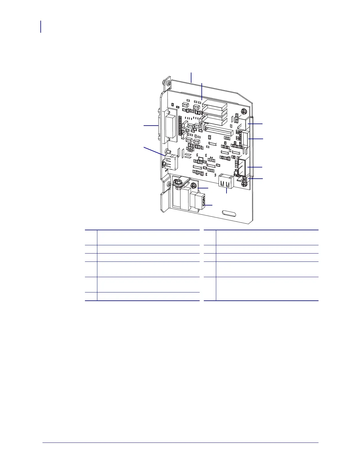
1
Applicator interface board mounting
plate
7
J7: Internal HDMI connector for
control panel
2
Applicator interface board
8
Voltage regulator board
3
J3: Applicator interface power cable
9
J1 (on voltage reg. board): Power cable
4
J1: Locking SP comm cable
10
J2: External HDMI connector for
deported control panel
5
J8: Control panel SPI extension
(ribbon) cable
11
J6: Applicator interface cable
6
J9: Door-open sensor cable