151
Applicator Interface Board Reconfiguration
Changing Jumper Settings for Isolated Mode
8/23/12 P1051584-002
Adjust Jumper Placement for +5V to +28V Isolated Mode
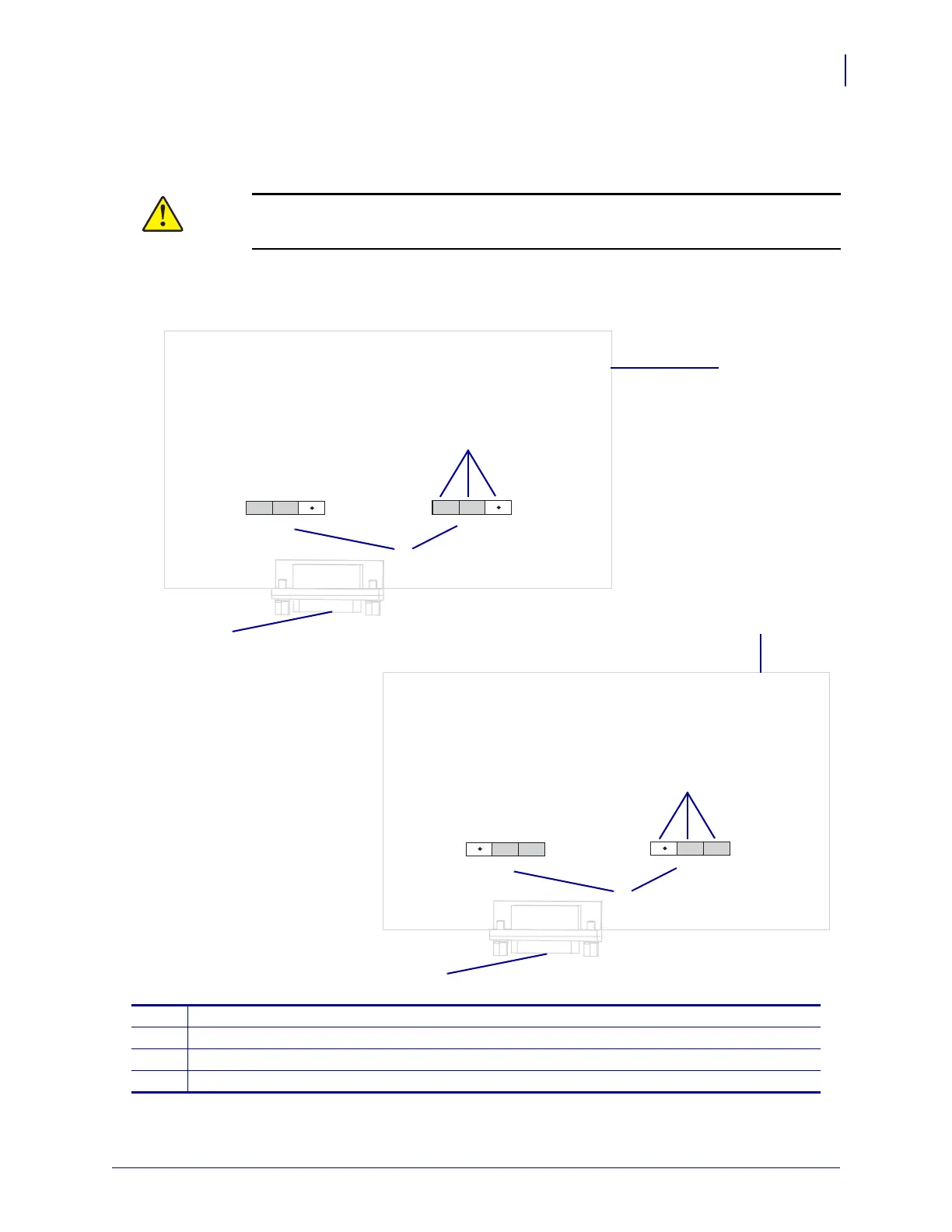
13. Locate the areas marked J4 and J5.
14.
Caution • Do not apply external power until after the board is reconfigured for Isolated
Mode.
Move the jumpers on both J4 and J5 to cover the pins as shown from the default of
Non-Isolated Mode to Isolated Mode. You may use needle-nose pliers, if necessary.
1
Simulated applicator interface board
2
Pins
3
Labels on the applicator interface board
4
Applicator port
INT +5V
EXT +V
INT
GND
EXT GND
J5
J4
INT +5V
EXT +V
INT
GND
EXT GND
J5
J4
2
3
Key
Gray: Jumper position
White: Not Connected
NON-ISOLATED MODE (Default Setting)
Internal Supply, +5V
ISOLATED MODE
External Supply, +5V to +28V
1
1
2
3
4
4