Applicator Interface Board Reconfiguration
Changing Jumper Settings for Isolated Mode
152
P1051584-002 8/23/12
Reinsert and Reconnect the Applicator Interface Board
15. Gently insert the applicator interface board into the print engine, and slide it toward the
back plane.
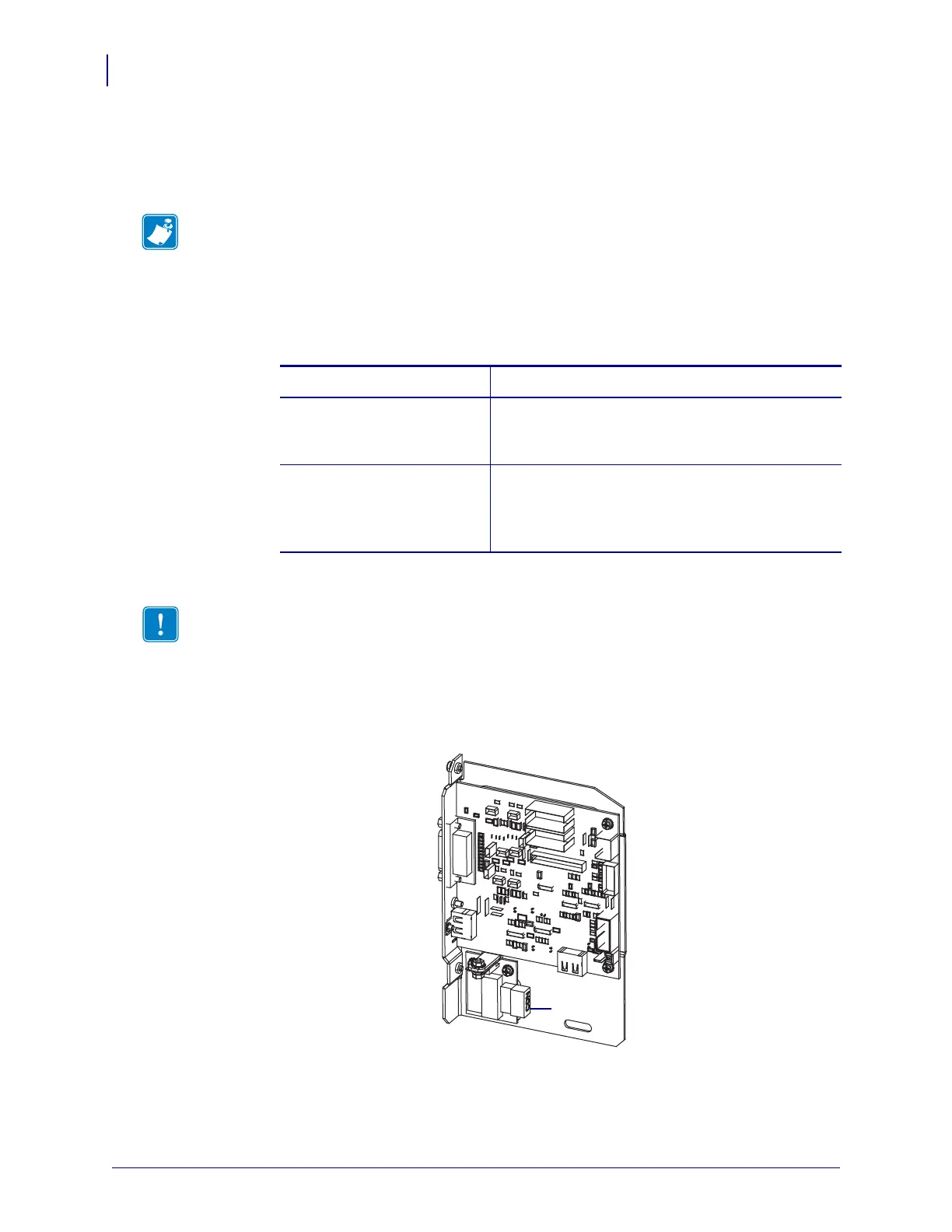
16. Reconnect the cables that were disconnected in step 9 and step 11. See Figure 20
on page 153 for most of the connector locations.
a. Reconnect the control panel.
Which type of control panel are you using?
b. Connect the locking SP comm cable to J1 on the applicator interface board.
c. Connect the six-pin connector for the power cable to J3 on the applicator interface
board.
d. Connect the four-pin connector (arranged in a line) for the power cable to J1 (1) on
the voltage regulator board.
e. Connect the door-open sensor to J9 on the applicator interface board.
Note • Avoid disconnecting or pinching any cables inside the electronics enclosure.
If your control panel is… Then…
Standard
(attached to the top of the
print engine)
1. Connect the HDMI cable to J7 on the applicator
interface board.
2. Continue with step b.
Deported
(attached away from the print
engine)
1. Reconnect the HDMI cable to J2 on the
applicator interface board. This connector is
accessible from the back plane.
2. Continue with step b.
Important • This applicator interface board requires the use of an SP comm cable
with a ferrite. The locking connector is the one closest to the ferrite.