SK=léÉê~íáçå
fåëíêìÅíáçå=j~åì~ä=`êçëëÄÉ~ã=PQM=ÉåMOE`loF =UR=çÑ=N PQ
pÉííáåÖ=pbj=é~ê~ãÉíÉêë
6.6.2. Setting detection parameters
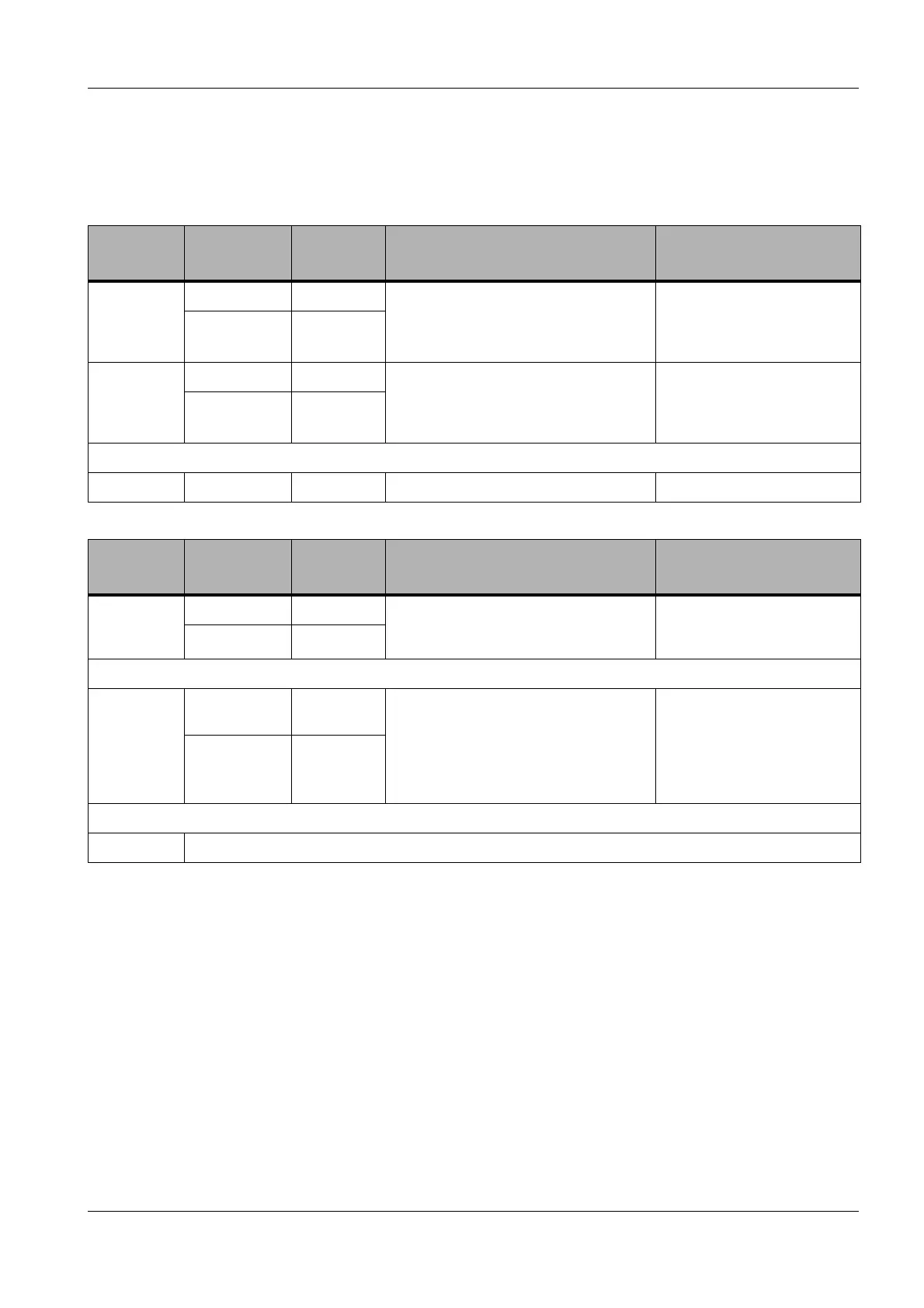
The following tables serves as a help to find the required settings for your application.
Standard
detectors
EHT
Typical
WD
Detector settings Remarks
In-lens SE 100 V max. 2 mm None Avoid strong specimen tilting.
This detector may be replaced
by the In-lens Duo detector.
100 V - 20 kV max. 6 mm
SE2 500 V - 5 kV 2 - 8 mm Collector bias adjustable from -250 V to
+ 400 V.
Standard applications: +300 V
Pseudo BSE image: -250 V to -50 V
Select the settings as
described in section 6.6.2.2..
5 kV - 30 kV min. 6 mm
VPSE
Optional
detectors
EHT
Typical
WD
Detector settings Remarks
In-lens Duo
SE Mode
100 V max. 2 mm None Avoid strong specimen tilting.
100 V - 20 kV max. 6 mm
In-lens Duo
BSE Mode
100 V - 1 kV 1-2 mm Filtering grid adjustable from
0 V to +1500 V.
Value depends on type of electrons to be
detected:
less than approx. 800 V: SE + BSE
more than approx. 800 V: BSE
Avoid strong specimen tilting.
1 kV - 5 kV max. 6 mm
SESI refer to section 6.6.2.4.