EasyManuals Logo

ZOLL E Series Service Manual

ZOLL E Series
280 pages
To Next Page IconTo Next Page
To Previous Page IconTo Previous Page
Page #139 background imageLoading...
Page #139 background image
E Series Service Manual
9650-1450-01 Rev. D 5-29
Connector Panel Removal
Note: There are 2 styles of SPO2 connector (MS-11 & MX-1) used on the E Series, use the appropriate instructions for disassembly.
1. (MS-11 Style) Remove the 2 screws securing the panel to the
housing.
2. Lift assembly out, gently sliding rubber ground sleeve off
mounting post.
3. Remove rubber gasket (black foam) from connector panel. ECG
and SPO2 connectors can now be removed.
Note: During reassembly ensure conductive sleeve is in place next to SPO2
connector.

Table of Contents

Questions and Answers:

Question and Answer IconNeed help?

Do you have a question about the ZOLL E Series and is the answer not in the manual?
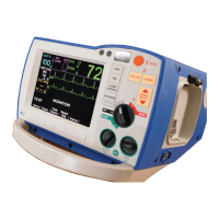
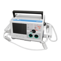
ZOLL E Series Specifications

General IconGeneral
Display TypeColor LCD
ECG MonitoringYes
PacingYes
Pacing Rate30-180 ppm
SpO2Optional
NIBPOptional
EtCO2Optional
PrinterIntegrated
Data ManagementYes
CPR FeedbackYes
IP RatingIP55
Pacing Output0 - 140 mA
Battery TypeRechargeable lithium ion
Battery Life4 hours
Energy Selection1-360 Joules
Display Size6.5 inches

Related product manuals