3D Systems, Inc.
36
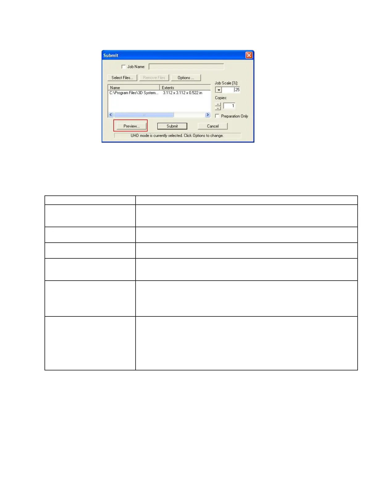
• Click Preview button on the Client's Submit dialog box. At least one part must be added for build in the Submit dialog box before
able to preview.
• Highlight a Job Name in modeler’s Info window, click Preview button or choose Job > Preview. When the preview window opens,
STL les can be added and removed, parts can be changed, rearranged, and submitted. The modied jobs can be sent directly to
the printer’s queue.
• The following are descriptions of each icon in print preview and their function.
Icon Tool Functions Description
Add Part Add a STL or CTL File. The system displays a le browser dialog box which you can
use to select one or more parts. Select open on the dialog box to add part to the print
preview platform.
Part Selections, Translation,Ro-
tation
Move parts in specied X and Y axis as well as in the X,Y coordinates. The parts must
be viewed in top, bottom left or right to manipulate them.
Submit Job See “Submit Job” section to understand how this function is used to submit a job. Once
a job is submitted it can be manipulated in print preview.
Trackball View Change the platform viewing area. Normal dragging (with the left mouse button pressed
down) rotates the viewing area. When using the right mouse button, the build envelope
can be dragged around within the viewing area.
Triangle Selection Select one or more individual triangular facets on parts. Afterwards, press the shift key
while clicking. If you select more than one facet on a single part, that part will not be
reoriented when you use the align facing button. You may nd it easier to select specic
triangles if viewing parts as wire frame. The 2-D views may also help nd the triangles
that you want to select.
Align Parts Facings Instead of manually rotating parts, you can select a triangle on the part and have the
system align the part until the selected triangle faces a desired direction: up, down, the
X-Z axis or the Y-Z axis.
Select a triangle using the triangle selection tool, the align facing buttons become
enable. Click the align part icons to rotate the part until the selected triangle faces the
selected direction. Triangles can be selected on several parts before clicking an align
Parts Facing icons so that all parts can be aligned together.
 Loading...