3D Systems, Inc.
38
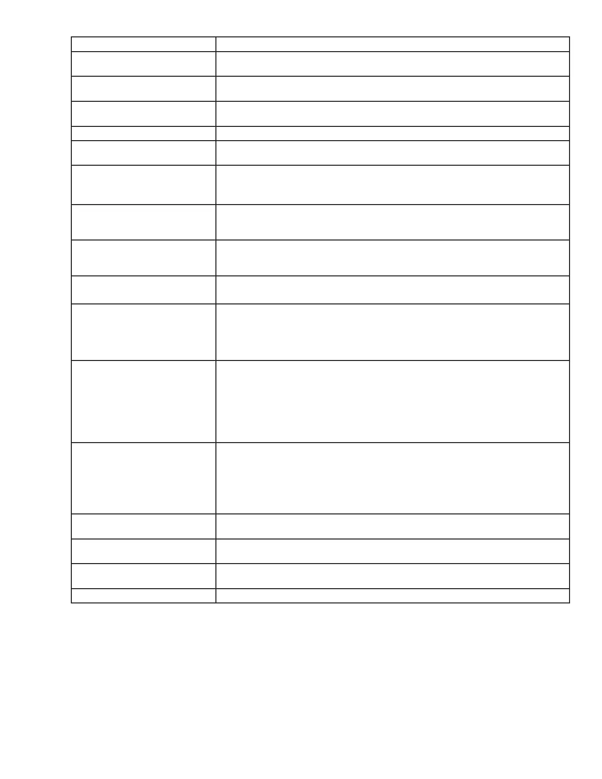
Icon Tool Functions Description
Isometric, Top, Front, Back, Left
Side, Right Side
Various view point of your part. Top and bottom views allow you to move the selected
parts on the build envelope.
View Platform and Parts This predened view zooms the view to include the entire build envelope and all the
parts on the platform..
View All Parts View all parts display the parts, and enlarges them as much as possible omitting empty
portions of the build envelope.
View Selected Parts View selected parts enlarges the selected parts until they ll the viewing area.
Delete To delete a part / parts from the platform, select a part using the “Select part” or “Select
all” tool and then click the delete icon to delete the selected part / parts.
Copy To copy a part, select part and click on the copy icon. A dialog box will appear asking for
the number of copies and the distance between them. Enter the number of copies and
distance, click Apply to generate the copies. .
Mirror To create a mirror image of one or several parts, select the parts and click the mirror
icon; the dialog box will appear. Choose an axis around which to mirror the part, and a
separation distance, click Apply.
Translate Use the translate part dialog box to move parts by entering inch values. The dialog box
allows relative movement (parts are moved from their current location in specied X
and Y axis) as well as absolute (parts are specied in the specied X,Y coordinates).
Rotate Select the part to rotate and click on the rotate icon. Use the dialog box to rotate the
degree amount in Y,X,Z directions in the maximum of 180°. .
Scale Parts can be scaled by percentages either by isometric meaning all axes get the same
scale factor or differently in each axis. Select one or several parts and click on the scale
icon; the dialog box appears. Enter a scale value, then click the apply. Scale values are
absolute. A value of 100% always returns the object to its original scale; 200% is always
twice the size of the original.
Align Parts Facings/
Align Parts Facings/
Align Parts Facings/ X-Y
Align Parts Facings/ Y-Z
Instead of manually rotating parts, you can select a triangle on the part and have the
system align the part until the selected triangle faces a desired direction: up, down, the
X-Z axis or the Y-Z axis.
Select a triangle using the triangle selection tool, the align facing buttons become
enable. Click the align part icons to rotate the part until the selected triangle faces the
selected direction. Triangles can be selected on several parts before clicking an align
Part icons so that all parts can be aligned together.
Scale mm to inch / Scale inch
to mm
The parts unit can be changed from millimeters to inch by dividing 25.4 into the part
measurement or change from inch to millimeters by multiplying 25.4 to the part mea-
surement.
Select the part and click Scale to inch icon. A dialog box will ask if you want to proceed
with the modications; select “Yes” to proceed with the parts unit changes or select “No”
to discontinue.
Undo Click the undo icon to bring part back to its previous state after changes have been
made.
Verify Verication detects and xes problems in the STL. Also individual STL part can be veri-
ed by selecting it and then clicking the Verify icon.
Auto Part Placement This tool arranges parts for optimum build speed. Select the parts and click on auto
place. The parts will automatically arrange in the build envelope.
Estimate Build Time Click on the estimate build time icon to estimate the time it will take to build the part.
 Loading...