Parameters 199
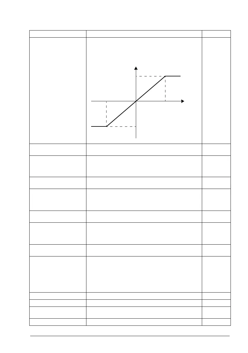
12.19 AI1 scaled at AI1
min
Defines the real internal value that corresponds to the
minimum analog input AI1 value defined by parameter 12.17
AI1 min. (Changing the polarity settings of 12.19 and 12.20
can effectively invert the analog input.)
0.000
-32768.000 …
32767.000
Real value corresponding to minimum AI1 value. 1 = 1
12.20 AI1 scaled at AI1
max
Defines the real internal value that corresponds to the
maximum analog input AI1 value defined by parameter 12.18
AI1 max. See the drawing at parameter 12.19 AI1 scaled at
AI1 min.
50.0
-32768.000 …
32767.000
Real value corresponding to maximum AI1 value. 1 = 1
12.21 AI2 actual value Displays the value of analog input AI2 in mA or V (depending
on whether the input is set to current or voltage by a hardware
setting).
This parameter is read-only.
-
-22.000 … 22.000
mA or V
Value of analog input AI2. 1000 = 1 mA
or V
12.22 AI2 scaled value Displays the value of analog input AI2 after scaling. See
parameters 12.29 AI2 scaled at AI2 min and 12.30 AI2 scaled
at AI2 max.
This parameter is read-only.
-
-32768.000 …
32767.000
Scaled value of analog input AI2. 1 = 1
12.25 AI2 unit selection Selects the unit for readings and settings related to analog
input AI2.
Note: This setting must match the corresponding hardware
setting on the drive control unit (see the hardware manual of
the drive). Control board reboot (either by cycling the power
or through parameter 96.08 Control board boot) is required to
validate any changes in the hardware settings.
mA
VVolts. 2
mA Milliamperes. 10
12.26 AI2 filter time Defines the filter time constant for analog input AI2. See
parameter 12.16 AI1 filter time.
0.100 s
0.000 … 30.000 s Filter time constant. 1000 = 1 s
No. Name/Value Description Def/FbEq16
12.20
12.18
12.17
12.19
AI
in
(12.11)
AI
scaled
(12.12)

 Loading...


