212 Parameters
250 us 250 microseconds. 2
500 us 500 microseconds. 3
1 ms 1 millisecond. 4
2 ms 2 milliseconds. 5
4 ms 4 milliseconds. 6
7.9375 ms 7.9375 milliseconds. 7
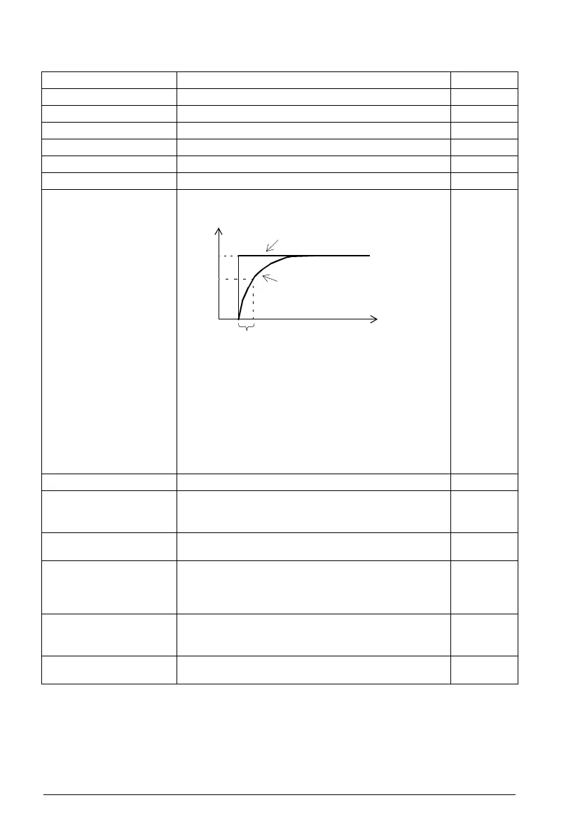
14.32 AI1 filter time (Visible when 14.01 Module 1 type = FIO-11 or FAIO-01)
Defines the filter time constant for analog input AI1.
Note: The signal is also filtered due to the signal interface
hardware. See parameter 14.31 AI1 filter gain.
0.100 s
0.000 … 30.000 s Filter time constant. 1000 = 1 s
14.33 AI1 min (Visible when 14.01 Module 1 type = FIO-11 or FAIO-01)
Defines the minimum value for analog input AI1.
See also parameter 14.21 AI tune.
0.000 mA or
V
-22.000 … 22.000
mA or V
Minimum value of AI1. 1000 = 1 mA
or V
14.34 RO1 source (Visible when 14.01 Module 1 type = FIO-01 or FDIO-01)
Selects a drive signal to be connected to relay output RO1.
For the available selections, see parameter 14.11 DIO1
output source.
Not
energized
14.34 AI1 max (Visible when 14.01 Module 1 type = FIO-11 or FAIO-01)
Defines the maximum value for analog input AI1.
See also parameter 14.21 AI tune.
10.000 mA or
V
-22.000 … 22.000
mA or V
Maximum value of AI1. 1000 = 1 mA
or V
No. Name/Value Description Def/FbEq16
63
%
100
T
t
O = I × (1 - e
-t/T
)
I = filter input (step)
O = filter output
t = time
T = filter time constant
Unfiltered signal
Filtered signal

 Loading...


