Parameters 405
Dataset 24/25 Data sets 24 and 25. 1
60.65 DDCS controller
comm supervision
force
Activates DDCS controller communication monitoring
separately for each control location (see section Local control
vs. external control on page 24).
The parameter is primarily intended for monitoring the
communication with the controller when it is connected to the
application program and not selected as a control source by
drive parameters.
0000b
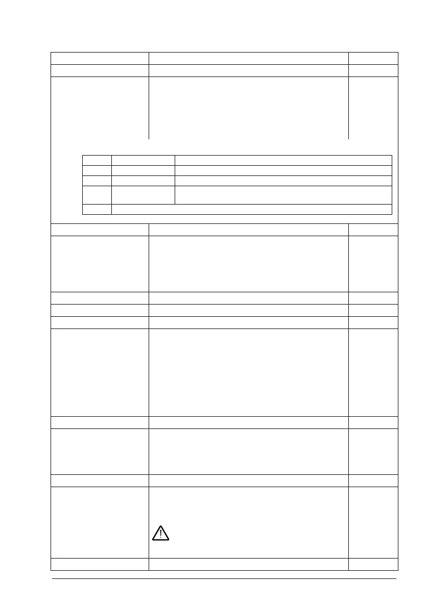
0000b…0111b DDCS controller communication monitoring selection. 1 = 1
60.71 INU-LSU
communication port
(Only visible when supply unit control activated by 95.20)
Selects the DDCS channel used for connecting to another
converter (such as a supply unit).
The selections available, as well as the default, depend on
drive hardware.
See also section Control of a supply unit (LSU) (page 77).
see text
Not in use None (communication disabled). 0
RDCO CH 1 Channel 1 on RDCO module. 11
DDCS via BC Connector X201. 15
60.77 INU-LSU link
control
(Only visible when supply unit control activated by 95.20)
Defines the light intensity of the transmission LED of RDCO
module channel CH1. (This parameter is effective only when
parameter 60.71 INU-LSU communication port is set to
RDCO CH 1. FDCO modules have a hardware transmitter
current selector.)
In general, use higher values with longer fiber optic cables.
The maximum setting is applicable to the maximum length of
the fiber optic link. See Specifications of the fiber optic
master/follower link (page 74).
10
1…15 Light intensity.
60.78 INU-LSU comm
loss timeout
(Only visible when supply unit control activated by 95.20)
Sets a timeout for communication with another converter
(such as the supply unit). If a communication break lasts
longer than the timeout, the action specified by parameter
60.79 INU-LSU comm loss function is taken.
100 ms
0…65535 ms Timeout for communication between converters.
60.79 INU-LSU comm
loss function
(Only visible when supply unit control activated by 95.20)
Selects how the inverter unit reacts to a communication break
between the inverter unit and the other converter (typically
the supply unit).
WARNING! With settings other than Fault, the inverter
unit will continue operating based on the status
information that was last received from the other
converter. Make sure this does not cause danger.
Fault
No action No action taken. 0
No. Name/Value Description Def/FbEq16
Bit Name Value
0 Ext 1 1 = Communication monitoring active when Ext 1 is being used.
1 Ext 2 1 = Communication monitoring active when Ext 2 is being used.
2 Local 1 = Communication monitoring active when local control is being
used.
3…15 Reserved

 Loading...


