INSTALLATION PROCEDURES
FOX615Installation 41
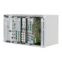
Figure 21: FOX615 fixing positions in the 19-inch rack relative to the
cable tray
Legend:
1 Cable tray with captive nuts at positions (11), (12)
2 Subrack with captive nuts at positions (21), (22)
3 FAMO1 or FAMO1-F with captive nuts at positions (31), (32)
4 Heat deflection shield R7AI (optional) with captive nuts at posi-
tions (41), (42)
Captive nuts installation Proceed as follows:
1. Locate the fixing position of the FOX615 cable tray in the 19-inch rack
and fit 2 captive nuts at positions (11) and (12), left and right.
2. Locate the fixing position of the FOX615 subrack in the 19-inch rack and
fit 2 captive nuts at positions (21) and (22), left and right.
3. Optional: Locate the fixing position of the FAMO1 or FAMO1-F in the 19-
inch rack and fit 2 captive nuts at positions (31) and (32), left and right.
4. Locate the fixing position of the heat deflection shield R7AI (option) in
the 19-inch rack and fit 2 captive nuts at positions (41) and (42), left and
right.
End of instruction
44.45 mm
76.2 mm
190.5 mm
44.45 mm
31.75 mm
76.2 mm
12.7 mm
42
4
3
2
1
41
32
31
22
21
12
11