INSTALLATION PROCEDURES
FOX615Installation 61
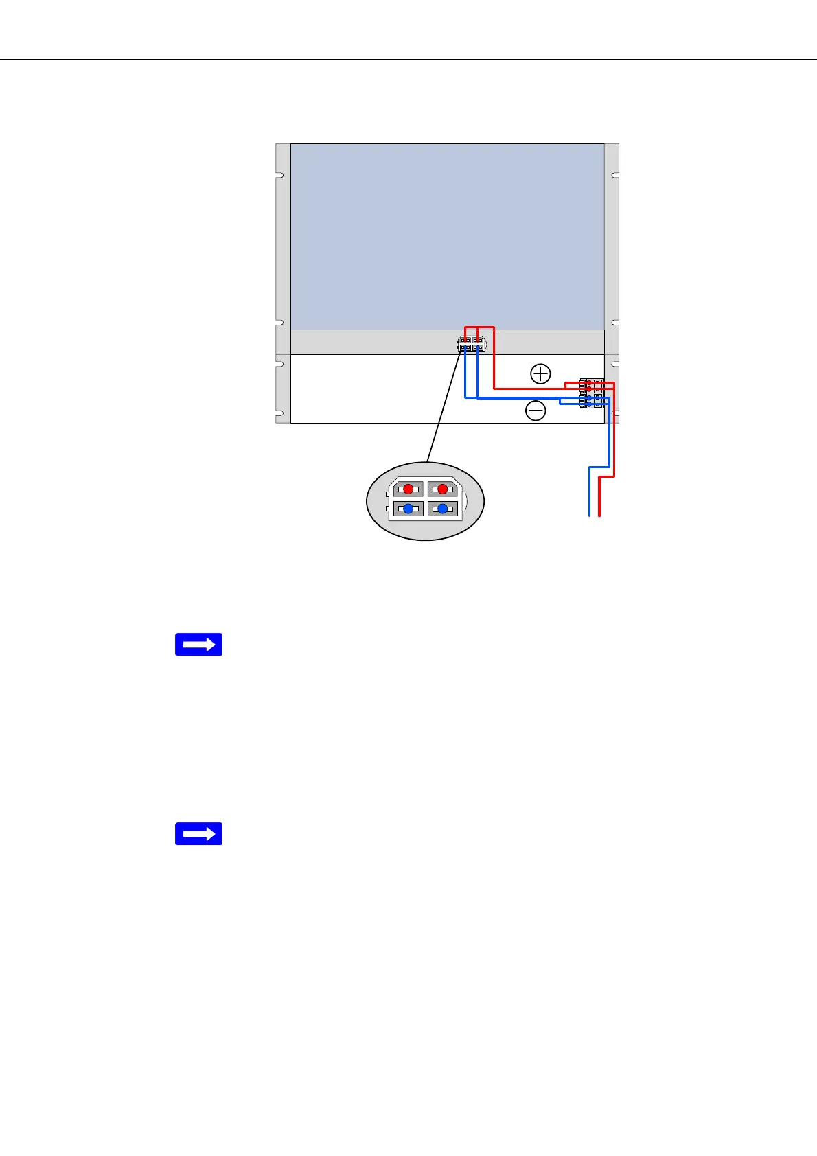
Figure 33: Principles of single circuit power supply
Legend:
PSC 1 Power Supply Circuit 1
The connector block “S
1
” is alternatively installed inside the right (as show in
Figure 24) or left side of the cable tray.
→ refer to section Installing the DC power supply (on page 43).
The short power cable “C
1
” connects the power interface “P
1
” of the FOX615
subrack to the connector block “S
1
” providing the external power supply cir-
cuit.
The red conductors (+) are on top when plugging the cable “C
1
” to the power
interface “P
1
” of the subrack.
Figure 33 shows the front connection of the external power supply circuit
(PSC 1).
It is also possible to implement the WAGO connector block (S
1
) for rear con-
nection of the power supply circuit. In this case the subrack power cable
leaves from the front and plus/minus polarities on the WAGO connector
block appear reversed compared to the presentation in Figure 33.
Power supply connection Proceed as follows:
1. Turn the TYCO connector of the power cable in such way that the red
cables are on top (connector key to the right).
2. Locate the TYCO connector in front of the power interface of the FOX
subrack.