INSTALLATION PROCEDURES
FOX615Installation 69
DUPF1 alarm interface con-
nection
Proceed as follows:
1. Tie the DUPF1 power and alarm cable from below the cable clamp (not
shown in Figure 41) along the right bracket of the subrack up to the
FAMO1 or FAMO1-F.
2. Plug the Molex connector to the F5 interface of the FAMO1 or FAMO1-F.
3. Secure the DUPF1 alarm cable in cable clamp (22).
4. Check the lock of the Molex connector for safe fit.
5. Arrange the cable in such a way that it does not block the fixing slots for
the subrack front cover in the brackets.
End of instruction
The DUPF1 connector does not use the remaining 2 alarm inputs. If required
these inputs can be used for other alarm signals.
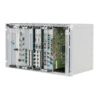
3.7.3.4 Alarm signal output interface
The FAMO1 or FAMO1-F provides the interface F2 for the output of the 2
system alarm signals:
• Service Affecting Alarm (SAA)
• Service Not affecting Alarm (SNA)
Figure 42: FAMO1 and FAMO1-F alarm signals output interface
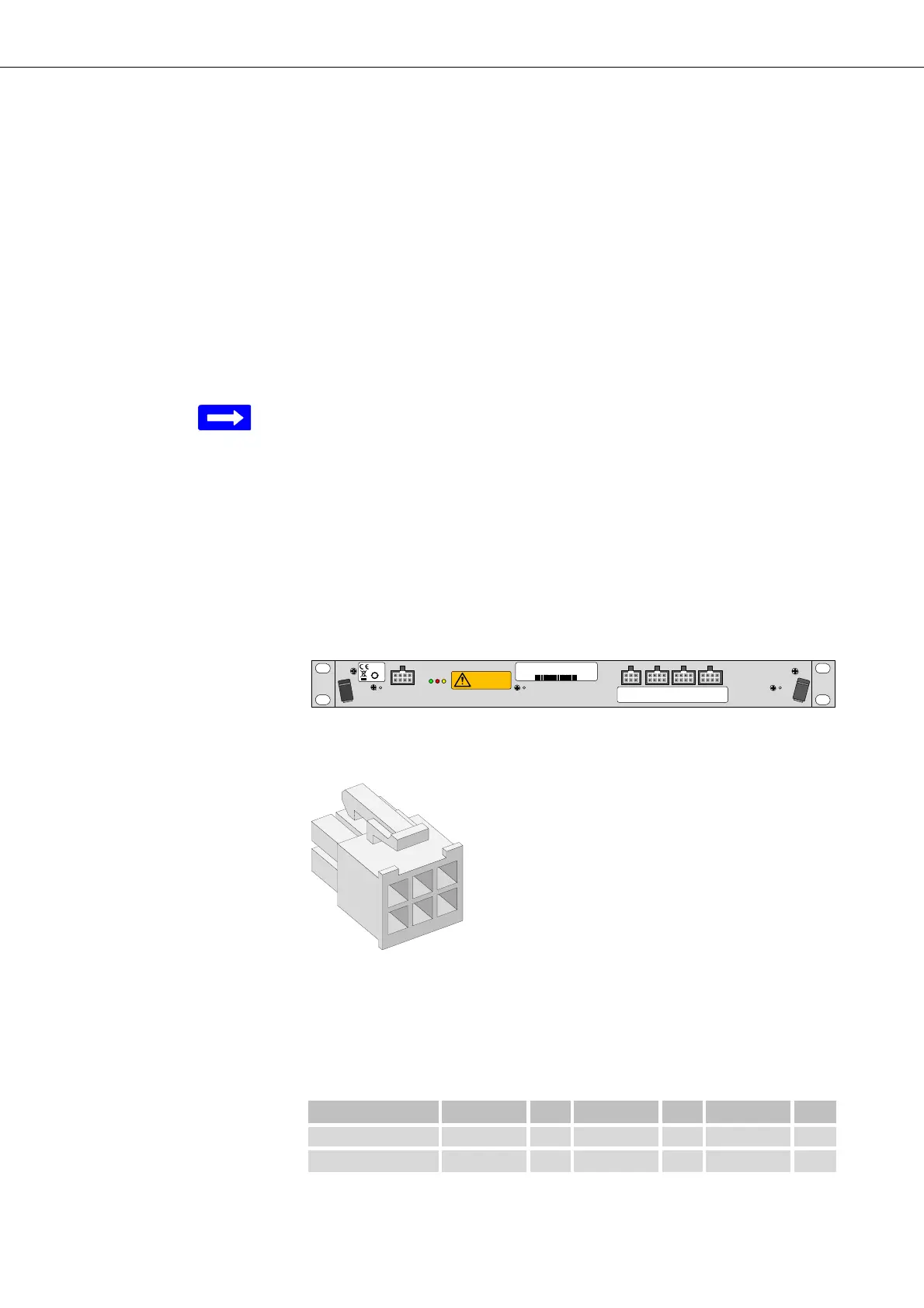
The alarm signal output interface F2 uses a pin assignment as follows:
Figure 43: Molex connector frame system alarm signal outputs
For the connection of alarm signals Mini-Fit HCS
TM
crimp terminals are
implemented within the Molex connector frame as described in the table
below.
SxA_make: The contact closes if the alarm becomes active = AC
F3: Alarm inputs
1-4
F4: Alarm inputs
5- 8
F5: Alarm inputs
9-12
F2: Al arm o u tp u t
1-2
50
moving fans
refer to handboo k
F2
fan 48 V DC 19 " 1U
37970003
R2A
2111743473
2011 W44
Table 8: Alarm output interface pin connection
Alarm Type Pin Pin Pin
Non Urgent SNA_make 6 SNA_break 5 SNA_com 4
Urgent SAA_break 3 SAA_make 2 SAA_com 1