INSTALLATION PROCEDURES
FOX615Installation 47
3.5 Signal cables
3.5.1 Tying signal cables to the cable tray
The cable tray makes the installation of the external cabling for the units eas-
ier. It provides a means to arrange and fix the cables before the installation
of the subrack and thus provides space for convenient working.
On the front, the cable tray carries a label bar with numbers corresponding to
the slot positions of the subrack. It is essential that you align the position of
the connectors and cables for each unit and interface with respect to the
front line of the cable tray.
The signal cables have a common metallic braid shield for all the signal
leads of the cable. Depending on the unit and its traffic signals the signal
cable provides different EMC measures:
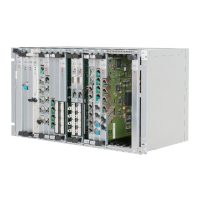
• Ferrite toroid near the connector (of the unit interface)
Figure 26: Cable with ferrite toroid sample
This scheme is used for interface cables which are generally shielded
from interface to interface such as
− Data circuits,
− etc.
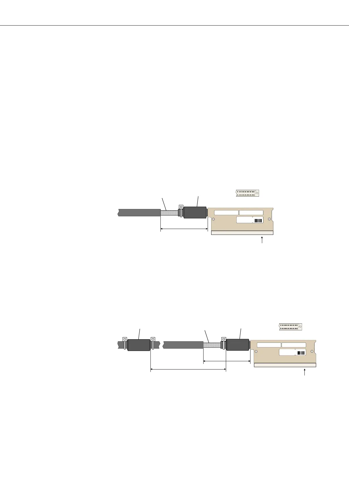
• EMC filter consisting of a ferrite toroid near the unit connector and a sec-
ond ferrite toroid
Figure 27: Cable with EMC filter sample
This scheme is used for interface cables which are not generally shielded
from interface to interface such as
− POTS circuits,
− ISDN circuits,
− etc.
For either cable, the exposed metallic braid shield is connected to the earth-
ing bar of the FOX subrack.
TSRBU 102 198 /XXXX
XXX
3. 3514 .198 / x x
XXXX
XXXXXXXX
B
Ferrite
Braid
Shield
70 mm
View B
TSRBU 102 198 /XXXX
XXX
3.3514 . 198 /xx
XXXX
XXXXXXXX
B
Ferrite
Braid
Shield
70 mm
View B
Ferrite
250 mm