CHECKLISTS
FOX615Installation 87
The alarm connector set contains the connector frames and crimp pins for 1
alarm signal output interface and 1 alarm signal input interface.
4.4.2 Computer cables and adapters
The connection of the control unit to the local craft device or to the manage-
ment communication structure (such as a LAN) requires standard computer
cables.
4.4.3 Signal cables
ABB provides cables for units with traffic interfaces. For most units one cable
connects all the interfaces of the unit.
For information about signal cables, refer to the user manuals of the units.
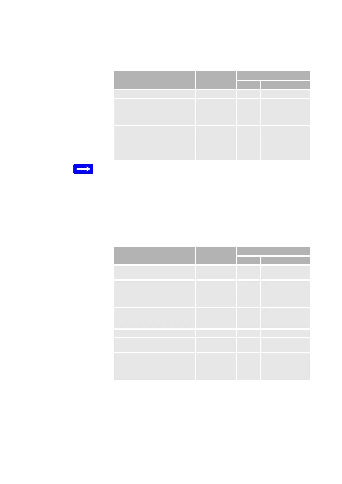
Table 12: Checklist alarm interface connector set
Description Identification Quantity
Units Remark
Connector set alarm interfaces:
- Alarm signal input
- Molex connector frame 2 x 4
- 8 Mini-Fit HCSTM crimp pins
(AWG 18 … AWG 24)
Connects 1 of the 3
FAMO1 or FAMO1-
F alarm input inter-
face groups
- Alarm signal output
- Molex connector frame 2 x 3
- 6 Mini-Fit HCSTM crimp pins
(AWG 18 … AWG 24)
Connects the alarm
output interface
group of the
FAMO1 or FAMO1-
F
Table 13: Checklist computer cables
Description Identification Quantity
Units Remark
Ethernet electrical cables: Uplink and/or man-
agement interfaces
FOX side:
- terminated RJ45, signals
crossed over [=], shielded, up to
1 Gbit/s
(4) Electrical interfaces
up to 4 per CESM1
FOX side:
- terminated RJ45, signals 1:1 [X],
shielded, up to 1 Gbit/s
(4) Electrical interfaces
up to 4 per CESM1
Ethernet optical cables: Uplink and/or man-
agement interfaces
FOX side:
- SFP cage,
connector and fibre specification
depend on SFP module
(2) Optical interfaces
up to 2 per CESM1