INSTALLATION PROCEDURES
FOX615Installation 77
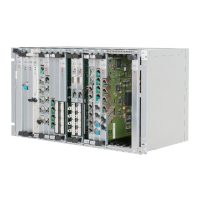
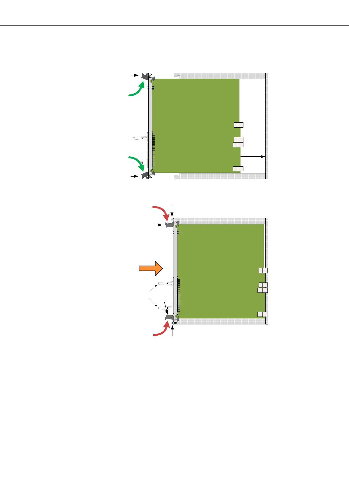
Figure 50: Insertion of units in the subrack
Legend:
BP Backplane with connectors
UR Upper Rail in the subrack
LR Lower Rail in the subrack
LC Latching clips (not available on all units!)
(for details of latching clip assembly, please refer to section
Connecting signal cables (on page 78)).
Unit insertion Proceed as follows:
1. Remove the cable clamp(s) from the earthing bar(s) of the subrack. Fol-
low steps (11) to (13) in Figure 47 for the right and/or the left side cable
clamps.
A
A
13
B
B
C
14
14
UR
LR
BP
UR
LR
BP
a)
b)
12
12
11
11
LC