INSTALLATION PROCEDURES
FOX615Installation 67
• Wire diameter: typ. 0.8 mm (AWG 20)
• Wire insulation diameter: 1.3 … 3.1 mm
For each connection you have to crimp a Mini-Fit HCS
TM
crimp terminal on
the corresponding cable. The crimp terminal is then inserted with the cable fit
into the Molex connector frame in the appropriate position.
A connector set with connector frames (1 frame 4x2, 1 frame 3x2) and crimp
terminals (14 Mini-Fit HCS
TM
) is available for optional alarm signal connec-
tions.
For details of the crimp process, refer to the instructions provided with the
crimp tool (for the crimp tool reference, refer to Table 15: Checklist for tools
(installation) (on page 89)).
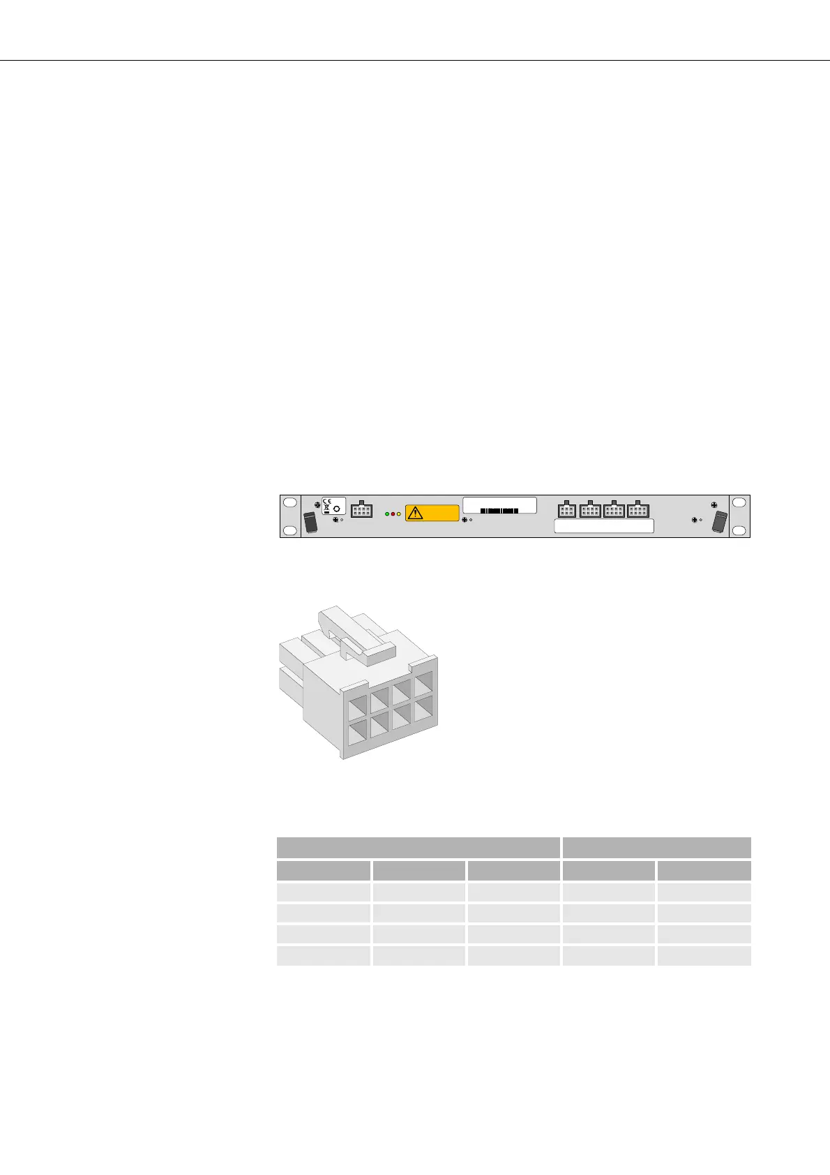
3.7.3.2 Alarm signal input interfaces
The FAMO1 or FAMO1-F provides 3 interfaces for the monitoring of alarm
signals (inputs) for totally 12 alarm signals. Each interface can handle up to
4 alarm signals.
Figure 39: FAMO1 and FAMO1-F alarm signals input interfaces
Each alarm interface F3, F4, F5 uses a pin assignment as follows:
Figure 40: Molex connector frame alarm signal inputs
Standard crimp contacts are connected and implemented within the individ-
ual Molex connector frames as required for monitored alarm signals.
If the DUPF1 is implemented it uses 2 of the 12 alarm inputs. For details,
refer to section DUPF1 alarm interface (on page 68).
F3: Alarm inputs
1-4
F4: Alarm inputs
5- 8
F5: Alarm inputs
9-12
F2: Al arm o u tp u t
1-2
50
moving fans
refer to handboo k
F3 F4 F5
fan 48 V DC 19 " 1U
37970003
R2A
2111743473
2011 W44
Table 6: Alarm input interfaces pin connection
Alarm Interface Connector Pin
F3 F4 F5 Signal GND
Alarm_in 1 Alarm_in 5 Alarm_in 9 8 4
Alarm_in 2 Alarm_in 6 Alarm_in 10 7 3
Alarm_in 3 Alarm_in 7 Alarm_in 11 6 2
Alarm_in 4 Alarm_in 8 Alarm_in 12 5 1