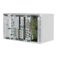
INSTALLATION PROCEDURES
FOX615Installation 45
4. Snap the studs of the block into the 2 holes from inside the cable tray,
while the cable tail is looking to the rear of the cable tray.
5. Check the WAGO connector block for firm fit.
6. Repeat steps 1 … 5 if you want to install a second power cable on the
opposite side of the cable tray for dual power source supply.
End of instruction
3.4.2.2 External power supply circuit
Hazardous electric currents. Risk of flashover and electric shock!
Make sure that
→ The external - 48/60 V
DC
power is switched off before you connect the
power leads to the WAGO connector block(s).
→ The power cables provide sufficient insulation (e.g. near the WAGO
connector block).
With life power supplies short circuits with flash over might result.
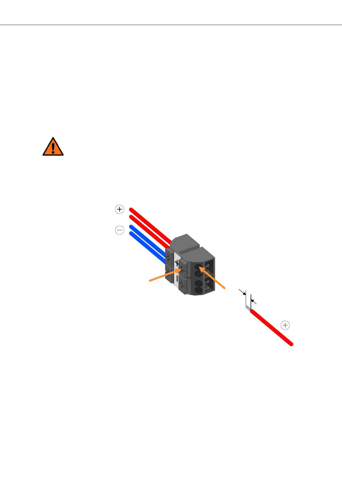
Figure 25: Connecting wires to the WAGO connector block
Legend to symbols of connector block:
+ 0 Volt conductor for power supply (red wires)
- - 48/60 Volt DC for power supply (blue wires)
External power supply circuit
connection
Proceed as follows:
1. Arrange the 2 wires (max. 4 mm
2
) with the negative voltage power sup-
ply and the 2 wires (max. 4 mm
2
) of the power return close to the WAGO
connector block installed on the cable tray.
2. Select the first wire of the power return (+).