INSTALLATION PROCEDURES
48 FOX615Installation
Depending on signal type and cable construction there are also cables with-
out ferrites implemented.
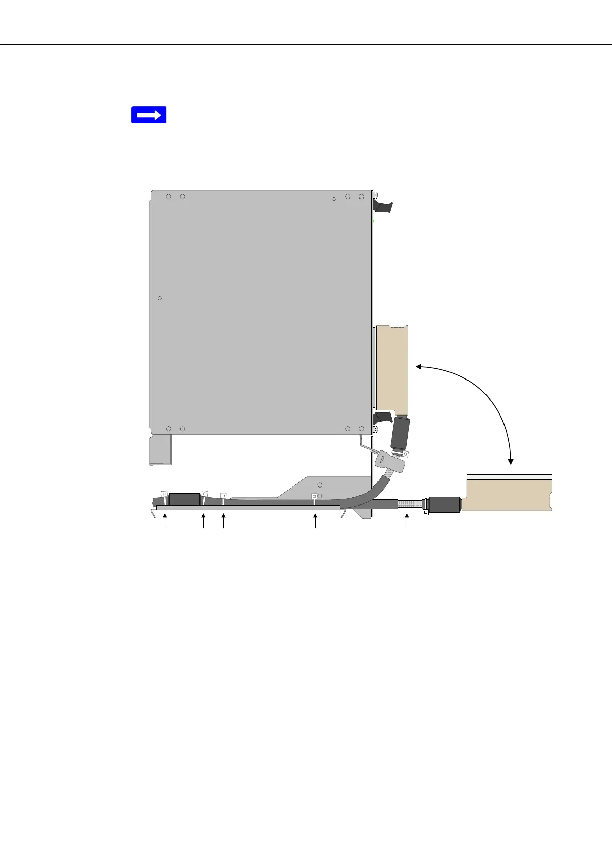
Figure 28 shows the cable installation on the cable tray.
Figure 28: Installation and position of connectors and cables with
EMC filter with respect to the front line of the cable tray
Legend:
1 Cable ties fixing the cable to the cable tray
2 Exposed part of the cable shield
The distance between the cable tray and the connector as well as the type of
the cable and connector depends on the plug-in unit (although identical for
most units and interfaces). The distance of the area with exposed cable
shield is constant with respect to the front line of the cable tray.
Installation of cables onto the
cable tray
Proceed as follows:
1. Label the cables with their respective slot number (as previously docu-
mented).
2. Align each cable on the cable tray with respect to the slot number.