INSTALLATION PROCEDURES
68 FOX615Installation
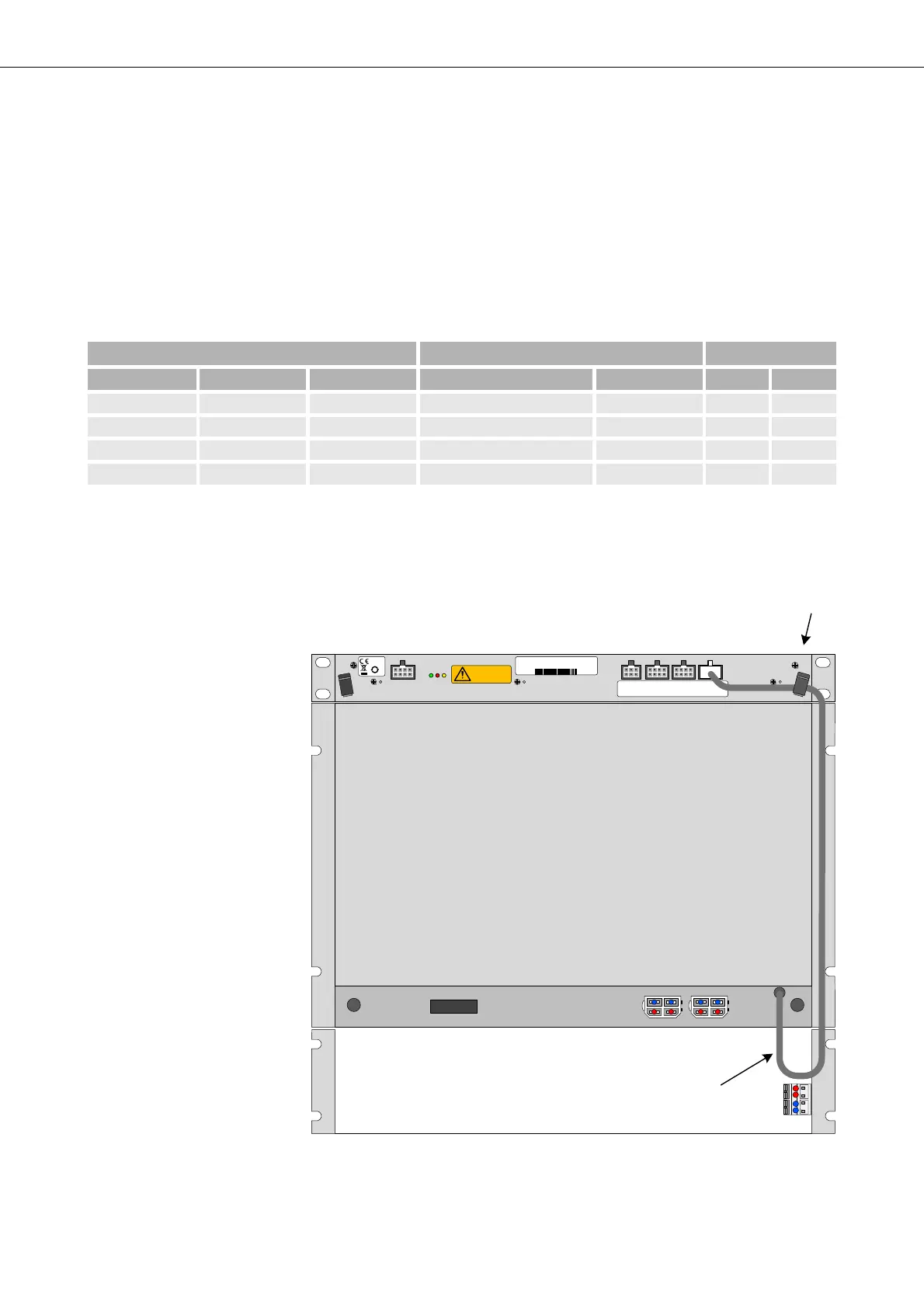
3.7.3.3 DUPF1 alarm interface
The DUPF1 provides a cable with a 4x2 way Molex connector for its alarm
signals. The DUPF1 alarms are connected to one of the 3 alarm interfaces
F3, F4, F5 on the FAMO1 or FAMO1-F, normally to the F5 interface. The
DUPF1 connects to the highest 2 inputs of the 4 alarm inputs provided via
the Molex connector:
The DUPF1 alarm outputs are implemented as “breaking” contacts, i.e. the
alarm signals provide ground potential if the alarm is inactive.
Figure 41: DUPF1 alarm interface connection
Table 7: DUPF1 alarm input interfaces pin connection
Alarm Interface DUPF1 interface Connector Pin
F3 F4 F5 Alarm Alarm active Signal GND
Alarm_in 1 Alarm_in 5 Alarm_in 9 not used 8 4
Alarm_in 2 Alarm_in 6 Alarm_in 10 not used 7 3
Alarm_in 3 Alarm_in 7 Alarm_in 11 Power supply PSC2 failed open 6 2
a
Alarm_in 4 Alarm_in 8 Alarm_in 12 Power supply PSC1 failed open 5 1
a
a. The DUPF1 alarm cable does not carry the GND potential. Only the wire with the
alarm signals is provided, using pin 5 and pin 6.
22
32
F3: Alarm inputs
1-4
F4: Alarm inputs
5- 8
F5: Alarm inputs
9-12
F2: Al arm o u tp u t
1-2
50
moving fans
refer to handboo k
F5
fan 48 V DC 19 " 1U
37970003
R2A
2111743473
2011 W 44