INSTALLATION PROCEDURES
54 FOX615Installation
3. Arrange the power connector (D
11
) and power cables of the DUPF1 in
such way that they take the position shown under b) in Figure 29.
The power connector is approximately in line with the left hand power
interface (D
2
) of the DUPF1.
This arrangement requires that you
− move the connector (D
11
) in directions (A) and (B)
− move and bend the (red) power cables in direction (C)
The alarm interface cable (52) and its connector (D
21
) must be free as
shown under b) in Figure 29.
4. Turn and align (D) the DUPF1 with the power cables in their position to
the lower edge (power interface) of the FOX subrack as shown under b)
in Figure 29.
5. Move (E) the DUPF1 with the power connector and cables in their posi-
tion close to the lower edge of the FOX subrack.
6. Plug (F) the power connector (D
11
) of the DUPF1 firmly to the power
interface (P
1
) of the FOX subrack (Figure 29, c)).
7. Align the 4 studs (11), (12), (13), (14) and 2 fixing screws (31), (32) on
the back of the DUPF1 in front of the corresponding slots (21), (22), (23),
(24) and treads (41), (42) in the subrack while checking that the DUPF1
power cable is still correctly folded well inside the DUPF1 shape (Figure
29, c)).
8. Move (G) the DUPF1 towards the subrack while inserting the 4 studs
(11), (12), (13), (14) into the corresponding slots (21), (22), (23), (24) in
the subrack (Figure 29, c)).
9. Press the DUPF1 against the FOX subrack and fix the left hand screw
(31) and the right hand screw (32) loosely (Figure 29, c)).
10. Check the DUPF1 power cable and the DUPF1 mechanics for correct fit-
ting to the subrack. Make sure that none of the power cables is clamped!
The alarm interface cable (52) and its connector (D
21
) must be free as
shown under b) in Figure 29.
Rearrange the power and alarm interface cables if required.
11. Tighten the screws (31) and (32).
End of instruction
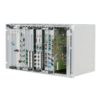
The FOX subrack with the DUPF1 installed is now one unit and must look as
shown in Figure 30: