INSTALLATION PROCEDURES
80 FOX615Installation
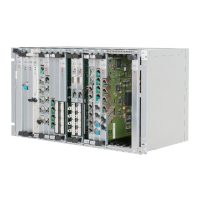
UR Upper Rail in the subrack
LR Lower Rail in the subrack
LC Latching clips (not available on all units!)
To remove units from the subrack you have to reverse the steps required for
the installation of units. Proceed as follows:
Unit removal Proceed as follows:
1. Remove the front cover from the subrack.
− Refer to Figure 53: Removing the front cover from the subrack (on
page 83) and proceed as instructed in the corresponding paragraphs.
2. Remove the cable clamp(s) from the subrack earthing bar(s).
− Refer to Figure 47: Cable clamps and earthing bars (conductive foam
in bars and clamps is dark shaded) (on page 73) and proceed as
instructed in the corresponding paragraphs for the left and/or the right
side cable clamps.
3. Unplug the connector(s) of the signal cable
− Check for latching clips (refer to positions (LC) in Figure 51) or other
strain relieve devices.
− Separate at the same time both clips (or other devices) from their
notch in the cover of the connector.
− Unplug the connector now.
4. Remove the unit (Figure 51)
− Unscrew both fixing screws (14) of the unit.
− To disengage the unit from the backplane connectors push both levers
(11) and (12) simultaneously in outward position (A). Allow the unit to
move outside while pressing on the levers.
− Remove (B) the unit from the subrack.
− Handle the unit according to the recommendations for ESD sensitive
devices.
5. Repeat the steps 3 to 4 for all units to remove.
End of instruction