MC96F6432
June 22, 2018 Ver. 2.9 119
11.4 Watch Timer
11.4.1 Overview
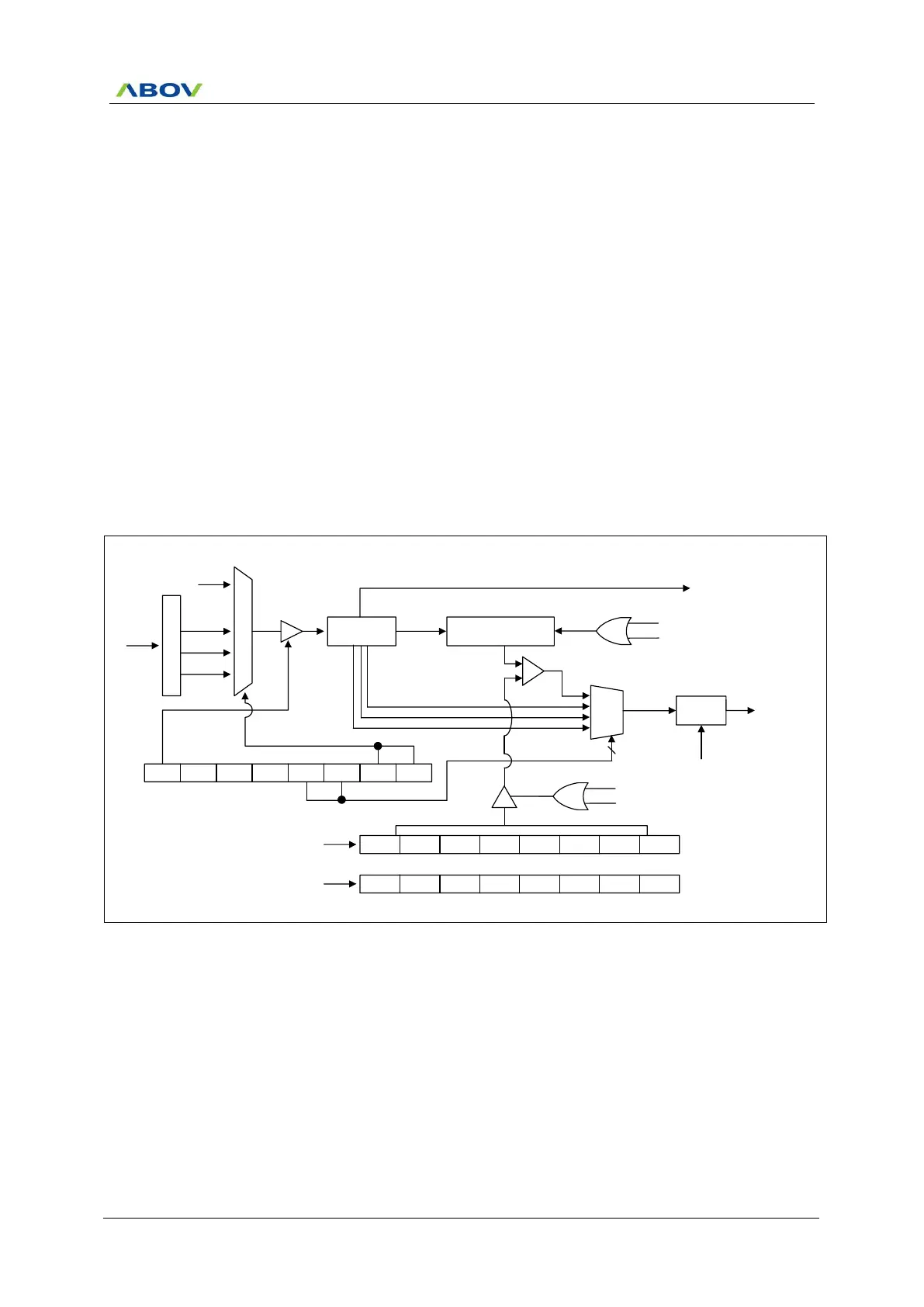
The watch timer has the function for RTC (Real Time Clock) operation. It is generally used for RTC design. The
internal structure of the watch timer consists of the clock source select circuit, timer counter circuit, output select
circuit, and watch timer control register. To operate the watch timer, determine the input clock source, output
interval, and set WTEN to ‘1’ in watch timer control register (WTCR). It is able to execute simultaneously or
individually. To stop or reset WT, clear the WTEN bit in WTCR register. Even if CPU is STOP mode, sub clock is
able to be so alive that WT can continue the operation. The watch timer counter circuits may be composed of 21-
bit counter which contains low 14-bit with binary counter and high 7-bit counter in order to raise resolution. In
WTDR, it can control WT clear and set interval value at write time, and it can read 7-bit WT counter value at read
time.
The watch timer supplies the clock frequency for the LCD driver (f
LCD
). Therefore, if the watch timer is disabled,
the LCD driver controller does not operate.
11.4.2 Block Diagram
P
r
e
s
c
a
l
e
r
fx
M
U
X
fSUB
fWCK
14Bit
Binary Counter
Timer counter
fWCK/2
14
WTCR WTEN
- -
WTIFR WTIN1 WTIN0 WTCK1 WTCK0
MUX
fWCK/2
14
fWCK/2
13
fWCK/2
7
WTIFR
To interrupt
block
WTCL WTDR6 WTDR5 WTDR4 WTDR3 WTDR2 WTDR1 WTDR0
WTDR
Write case
- WTCNT6 WTCNT5 WTCNT4 WTCNT3 WTCNT2 WTCNT1 WTCNT0
WTCNT
Read case
Clear
INT_ACK
fx/64
fx/128
fx/256
fLCD =1024Hz
2
fWCK
14
/(2 X(7 bit WTDR Value +1))
Comparator
match
Reload
Match
WTCL
Clear
Match
WTCL
Figure 11.5 Watch Timer Block Diagram