MC96F6432
284 June 22, 2018 Ver. 2.9
12.4 STOP Mode
The power control register is set to ‘03H’ to enter the STOP Mode. In the stop mode, the selected oscillator,
system clock and peripheral clock is stopped, but watch timer can be continued to operate with sub clock. With
the clock frozen, all functions are stopped, but the on-chip RAM and control registers are held. For example, If
the internal RC oscillator (fIRC) is selected for the system clock and the sub clock (fSUB) is oscillated, the internal
RC oscillator stops oscillation and the sub clock is continuously oscillated in stop mode. At that time, the watch
timer and LCD controller can be operated with the sub clock.
The source for exit from STOP mode is hardware reset and interrupts. The reset re-defines all the control
registers.
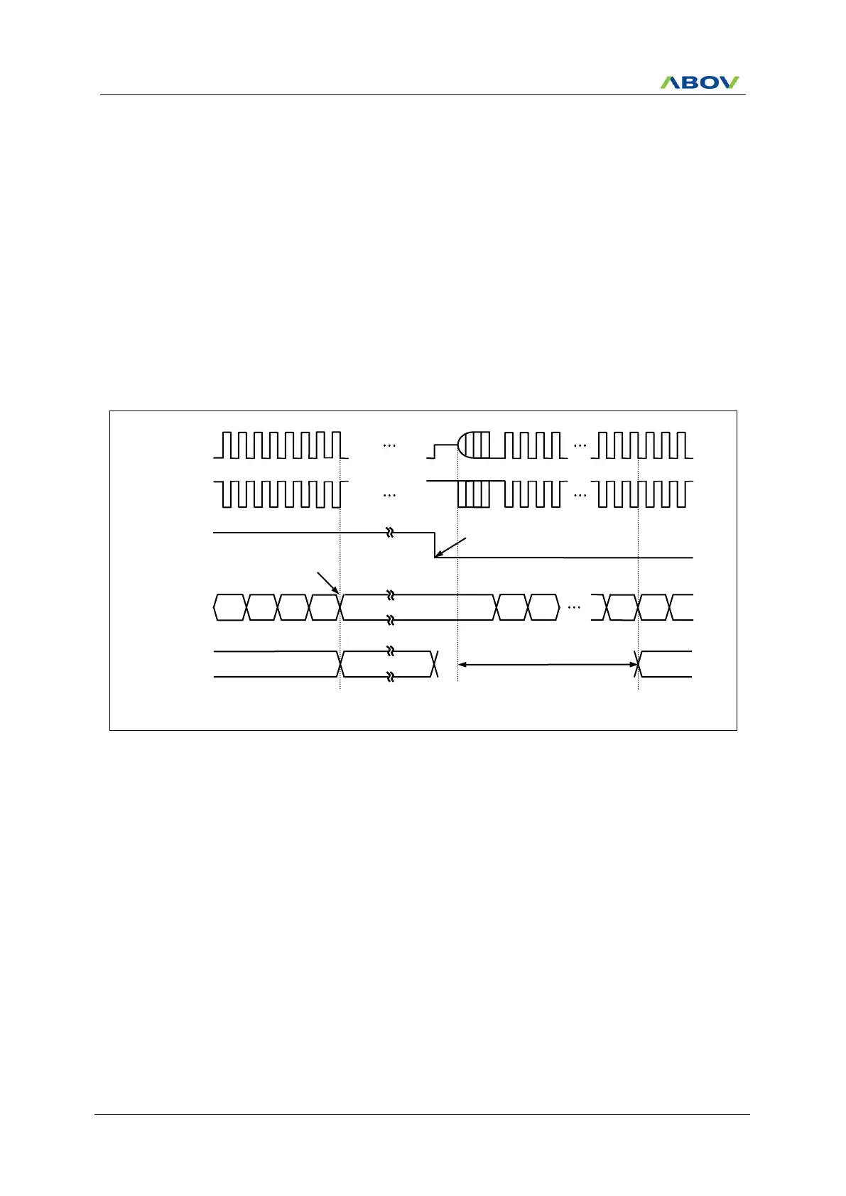
When exit from STOP mode, enough oscillation stabilization time is required to normal operation. Figure 12.2
shows the timing diagram. When released from STOP mode, the Basic interval timer is activated on wake-up.
Therefore, before STOP instruction, user must be set its relevant prescale divide ratio to have long enough time.
This guarantees that oscillator has started and stabilized.
Figure 12.2 STOP Mode Release Timing by External Interrupt
Before executed STOP instruction, BIT must be set
properly by software to get stabilization.