MC96F6432
144 June 22, 2018 Ver. 2.9
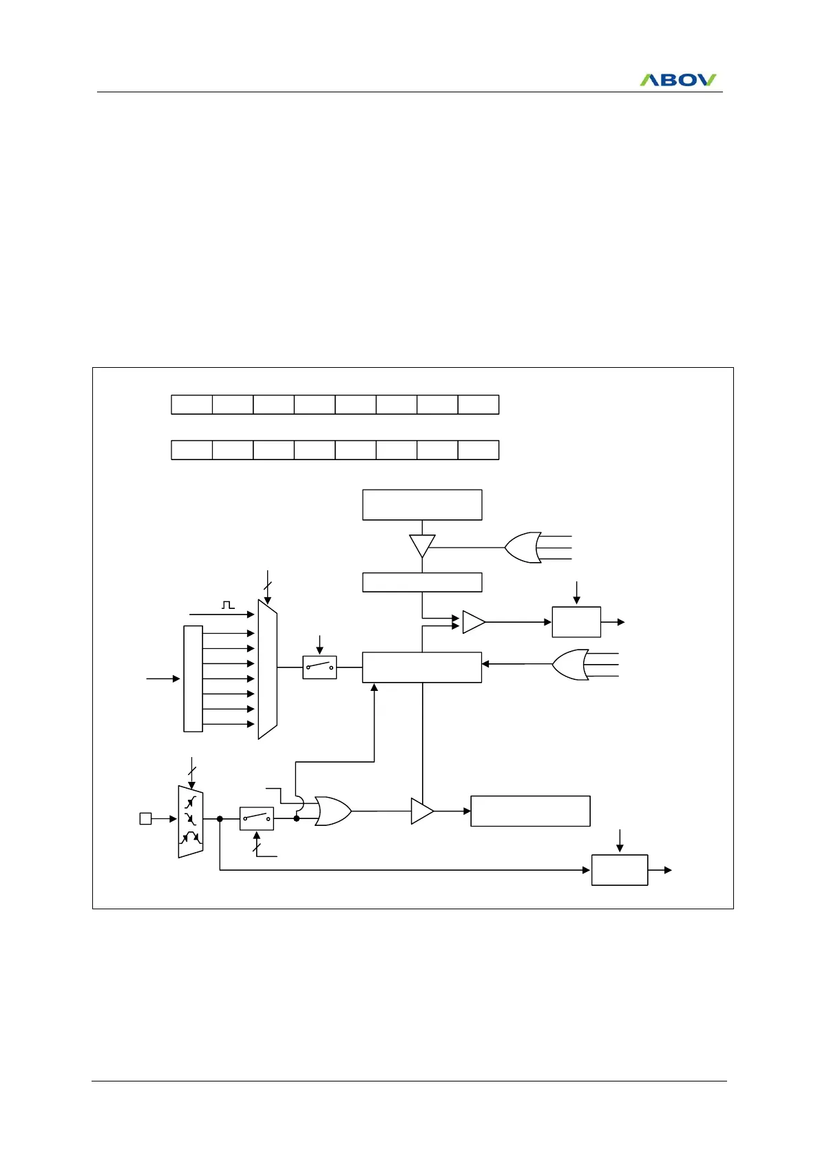
11.7.3 16-Bit Capture Mode
The timer 2 capture mode is set by T2MS[1:0] as ‘01’. The clock source can use the internal clock. Basically, it
has the same function as the 16-bit timer/counter mode and the interrupt occurs when T2CNTH/T2CNTL is equal
to T2ADRH/T2ADRL. T2CNTH/T2CNTL values are automatically cleared by match signal and it can be also
cleared by software (T2CC).
This timer interrupt in capture mode is very useful when the pulse width of captured signal is wider than the
maximum period of timer.
The capture result is loaded into T2BDRH/T2BDRL. In the timer 2 capture mode, timer 2 output(T2O) waveform
is not available.
According to EIPOL1 registers setting, the external interrupt EINT12 function is chosen. Of course, the EINT12
pin must be set to an input port.
A Match
T2CC
T2EN
P
r
e
s
c
a
l
e
r
fx
M
U
X
fx/2
fx/4
fx/32
fx/128
fx/512
fx/8
fx/1
16-bit Counter
T2CNTH/T2CNTL
16-bit B Data Register
T2BDRH/T2BDRL
Clear
T1 A Match
Comparator
16-bit A Data Register
T2ADRH/T2ADRL
T2IFR
INT_ACK
Clear
To interrupt
block
A Match
Buffer Register A
Reload
R
EINT12
T2CNTR
T2EN
3
T2CK[2:0]
Clear
FLAG12
(EIFLAG1.3)
INT_ACK
Clear
To interrupt
block
T2MS[1:0]
2
A Match
T2CC
T2EN
T2EN
T2CRH
1
ADDRESS:C3H
INITIAL VALUE : 0000_0000B
–
T2MS1 T2MS0
– – –
T2CC
–
0 1
– – –
X
T2CK2
T2CRL
X
ADDRESS:C2H
INITIAL VALUE : 0000_0000B
T2CK1 T2CK0 T2IFR
–
T2POL
–
T2CNTR
X X X
–
X
–
X
EIPOL1[7:6]
2
NOTE) T1 A Match is a pulse for the timer 2 clock source if it is selected.
Figure 11.24 16-Bit Capture Mode for Timer 2