MC96F6432
June 22, 2018 Ver. 2.9 141
11.7 Timer 2
11.7.1 Overview
The 16-bit timer 2 consists of multiplexer, timer 2 A data high/low register, timer 2 B data high/low register and
timer 2 control high/low register (T2ADRH, T2ADRL, T2BDRH, T2BDRL, T2CRH, T2CRL).
It has four operating modes:
- 16-bit timer/counter mode
- 16-bit capture mode
- 16-bit PPG output mode (one-shot mode)
- 16-bit PPG output mode (repeat mode)
The timer/counter 2 can be divided clock of the system clock selected from prescaler output and T1 A Match
(timer 1 A match signal). The clock source is selected by clock selection logic which is controlled by the clock
selection bits (T2CK[2:0]).
- TIMER 2 clock source: f
X
/1, 2, 4, 8, 32, 128, 512 and T1 A Match
In the capture mode, by EINT12, the data is captured into input capture data register (T2BDRH/T2BDRL). In
timer/counter mode, whenever counter value is equal to T2ADRH/L, T2O port toggles. Also the timer 2 outputs
PWM wave form to PWM2O port in the PPG mode.
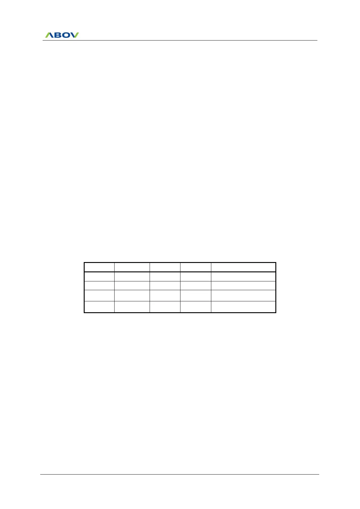
Table 11-9 Timer 2 Operating Modes
16 Bit Timer/Counter Mode
16 Bit PPG Mode
(one-shot mode)
16 Bit PPG Mode
(repeat mode)