MC96F6432
June 22, 2018 Ver. 2.9 93
10. Interrupt Controller
10.1 Overview
The MC96F6432 supports up to 23 interrupt sources. The interrupts have separate enable register bits
associated with them, allowing software control. They can also have four levels of priority assigned to them. The
non-maskable interrupt source is always enabled with a higher priority than any other interrupt source, and is not
controllable by software. The interrupt controller has following features:
- Receive the request from 23 interrupt source
- 6 group priority
- 4 priority levels
- Multi Interrupt possibility
- If the requests of different priority levels are received simultaneously, the request of higher priority level
is served first.
- Each interrupt source can be controlled by EA bit and each IEx bit
- Interrupt latency: 3~9 machine cycles in single interrupt system
The non-maskable interrupt is always enabled. The maskable interrupts are enabled through four pair of
interrupt enable registers (IE, IE1, IE2, IE3). Each bit of IE, IE1, IE2, IE3 register individually enables/disables the
corresponding interrupt source. Overall control is provided by bit 7 of IE (EA). When EA is set to ‘0’, all interrupts
are disabled: when EA is set to ‘1’, interrupts are individually enabled or disabled through the other bits of the
interrupt enable registers. The EA bit is always cleared to ‘0’ jumping to an interrupt service vector and set to ‘1’
executing the [RETI] instruction. The MC96F6432 supports a four-level priority scheme. Each maskable interrupt
is individually assigned to one of four priority levels according to IP and IP1.
Default interrupt mode is level-trigger mode basically, but if needed, it is possible to change to edge-trigger
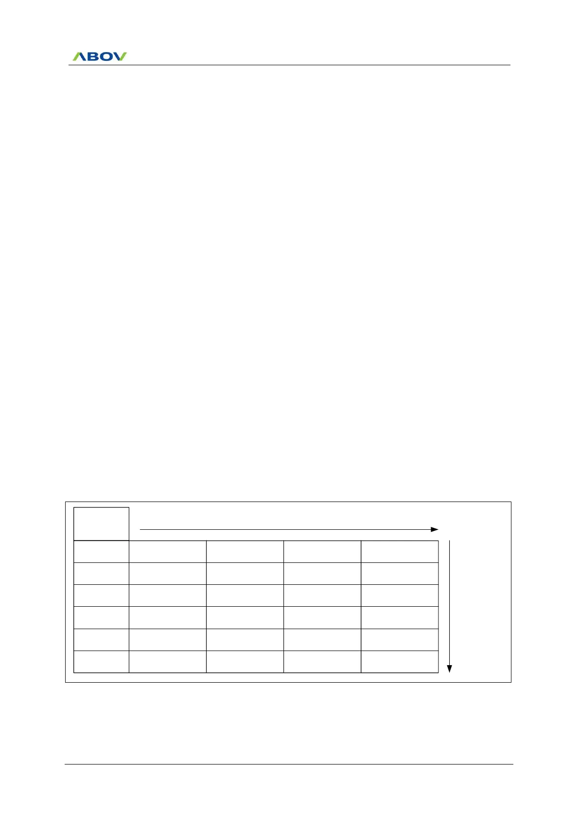
mode. Table 10-1 shows the Interrupt Group Priority Level that is available for sharing interrupt priority. Priority of
a group is set by two bits of interrupt priority registers (one bit from IP, another one from IP1). Interrupt service
routine serves higher priority interrupt first. If two requests of different priority levels are received simultaneously,
the request of higher priority level is served prior to the lower one.
Table 10-1 Interrupt Group Priority Level
0 (Bit0)
Interrupt
Group
1 (Bit1)
2 (Bit2)
3 (Bit3)
4 (Bit4)
5 (Bit5)
Interrupt 0 Interrupt 6 Interrupt 12 Interrupt 18
Interrupt 1 Interrupt 7 Interrupt 13 Interrupt 19
Interrupt 2 Interrupt 8 Interrupt 14 Interrupt 20
Interrupt 3 Interrupt 9 Interrupt 15 Interrupt 21
Interrupt 4 Interrupt 10 Interrupt 16 Interrupt 22
Interrupt 5 Interrupt 11 Interrupt 17 Interrupt 23
Highest
Lowest
Highest Lowest