EasyManuals Logo

Abov MC96F6332D User Manual

Default Icon
327 pages
To Next Page IconTo Next Page
To Previous Page IconTo Previous Page
Page #205 background imageLoading...
Page #205 background image
MC96F6432
June 22, 2018 Ver. 2.9 205
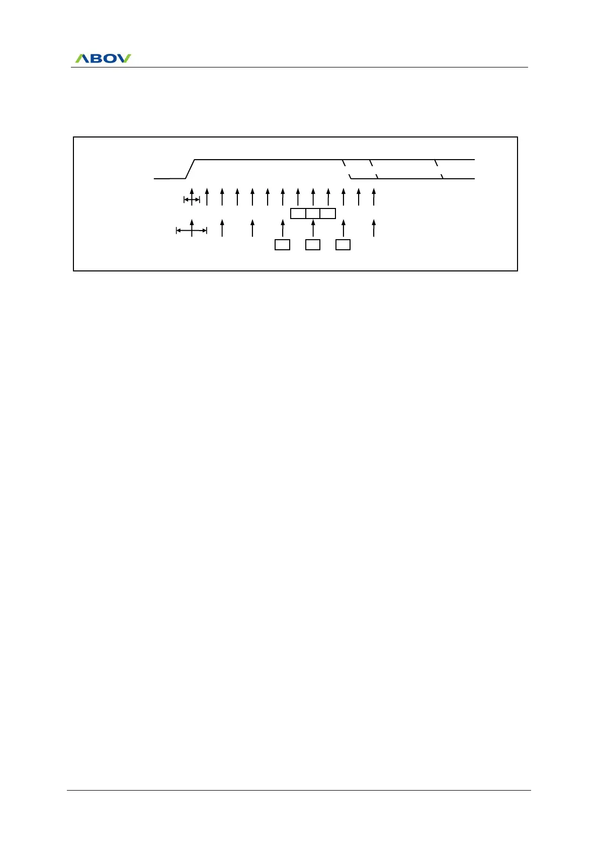
The process for detecting stop bit is like clock and data recovery process. That is, if 2 or more samples of 3
center values have high level, correct stop bit is detected, else a frame error (FE0) flag is set. After deciding
whether the first stop bit is valid or not, the Receiver goes to idle state and monitors the RXD0 line to check a
valid high to low transition is detected (start bit detection).
Figure 11.63 Stop Bit Sampling and Next Start Bit Sampling (USI0)
RXD0
1
2
3
4
5
6
7
8
9
10
11
12
13
STOP 1
1
2
3
4
5
6
7
Sample
(DBLS0 = 0)
Sample
(DBLS0 = 1)
(A)
(B)
(C)

Table of Contents

Questions and Answers:

Question and Answer IconNeed help?

Do you have a question about the Abov MC96F6332D and is the answer not in the manual?

Abov MC96F6332D Specifications

General IconGeneral
BrandAbov
ModelMC96F6332D
CategoryMicrocontrollers
LanguageEnglish

Related product manuals