EasyManuals Logo

Abov MC96F6332D User Manual

Default Icon
327 pages
To Next Page IconTo Next Page
To Previous Page IconTo Previous Page
Page #162 background imageLoading...
Page #162 background image
MC96F6432
162 June 22, 2018 Ver. 2.9
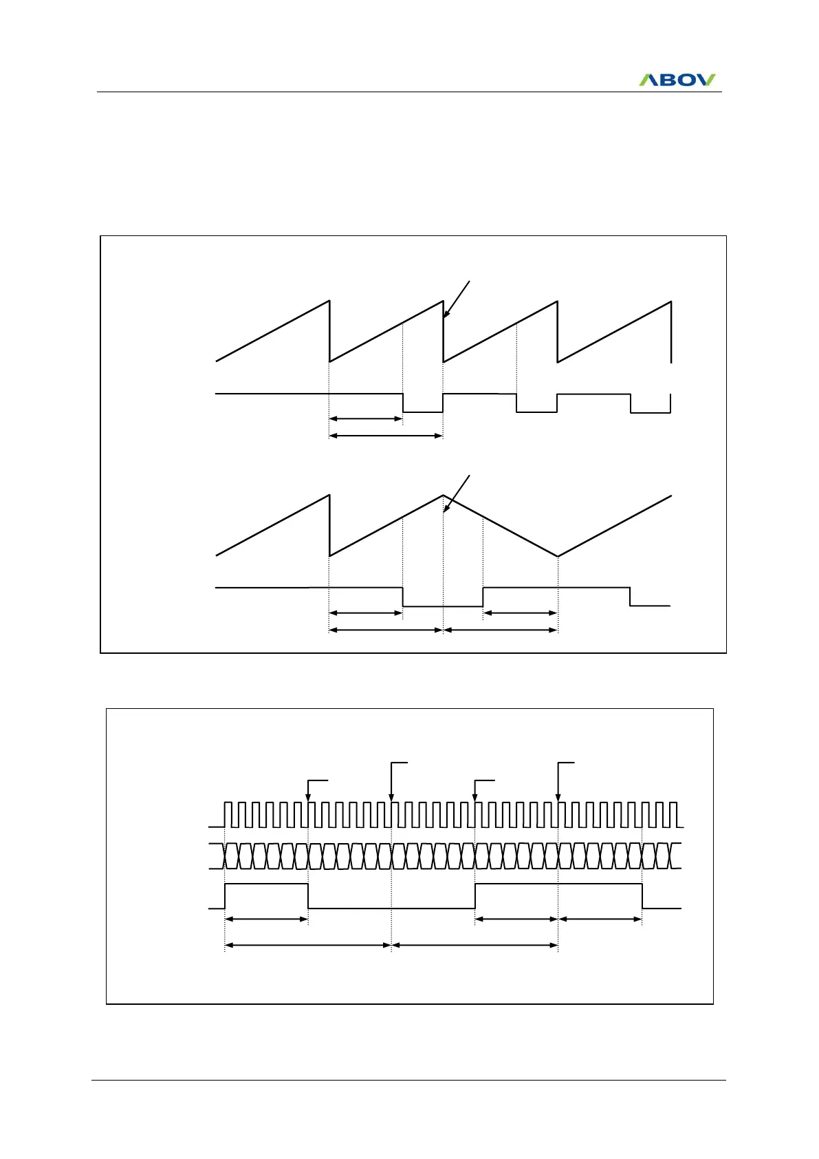
Phase correction & Frequency correction
On operating PWM, it is possible that it is changed the phase and the frequency by using BMOD bit (back-to-
back mode) in T4PCR1 register. (Figure 1.38, Figure 11.39, Figure 11.40 referred)
In the back-to-back mode, the counter of PWM repeats up/down count. In fact, the effective duty and period
becomes twofold of the register set values. (Figure 1.38, Figure 11.39 referred)
Figure 11.38 Example of PWM Output Waveform
Figure 11.39 Example of PWM waveform in Back-to-Back mode at 4 MHz
T4CNT
00
01
02
03
04
P02/PWM4AA
POLAA = 1
T4CR = 03
H
(2us)
T4PPRH = 00
H
T4PPRL = 0B
H
T4ADRH = 00
H
T4ADRL = 05
H
09
08
07
06
05
0A
0B
0B
0A
06
07
08
09
02
03
04
05
01
00
00
01
05
04
03
02
07
06
Source Clock
(f
X
)
08
Duty Cycle
(1+05
H
)X2us = 12us
Duty Cycle
(1+05
H
)X2us = 12us
Duty Cycle
(1+05
H
)X2us = 12us
Period Cycle
(1+0B
H
)X2us = 26us  38.46kHz
Start down Counter
Period Cycle
(1+0B
H
)X2us = 26us  38.46kHz
Duty match
detect
Start up Counter
Duty match
detect
T4CNT
Duty
Normal PWM
mode
Output
00
H
00
H
00
H
00
H
00
H
MAX
MAX
MAX
MAX
Period
Duty, Period
Update
T4CNT
Duty
Back-to-Back
mode
Output
00
H
00
H
00
H
MAX
MAX
MAX
Period
Duty, Period
Update
Duty
Period
Non Back-to-Back mode
Back-to-Back mode

Table of Contents

Questions and Answers:

Question and Answer IconNeed help?

Do you have a question about the Abov MC96F6332D and is the answer not in the manual?

Abov MC96F6332D Specifications

General IconGeneral
BrandAbov
ModelMC96F6332D
CategoryMicrocontrollers
LanguageEnglish

Related product manuals