MC96F6432
254 June 22, 2018 Ver. 2.9
9. This is the final step for master receiver function of I2C, handling STOP interrupt. The STOP bit
indicates that data transfer between master and slave is over. To clear USI1ST2, write “0” to USI1ST2.
After this, I2C enters idle state.
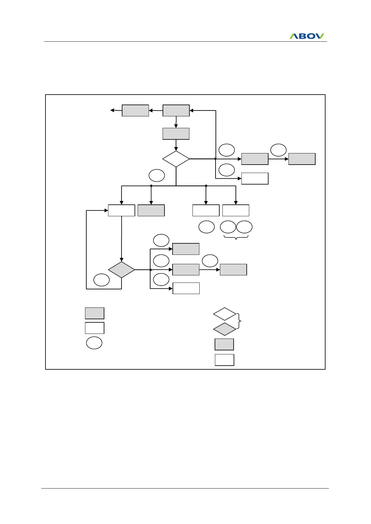
The processes described above for master receiver operation of I2C can be depicted as the following figure.
Figure 11.95 Formats and States in the Master Receiver Mode (USI1)
From master to slave /
Master command or Data Write
Interrupt, SCL1 line is held low
Interrupt after stop command
Arbitration lost as master and
addressed as slave
Slave Receiver (0x1D)
or Transmitter (0x1F)