MNR-310 System Administrator’s Manual
29
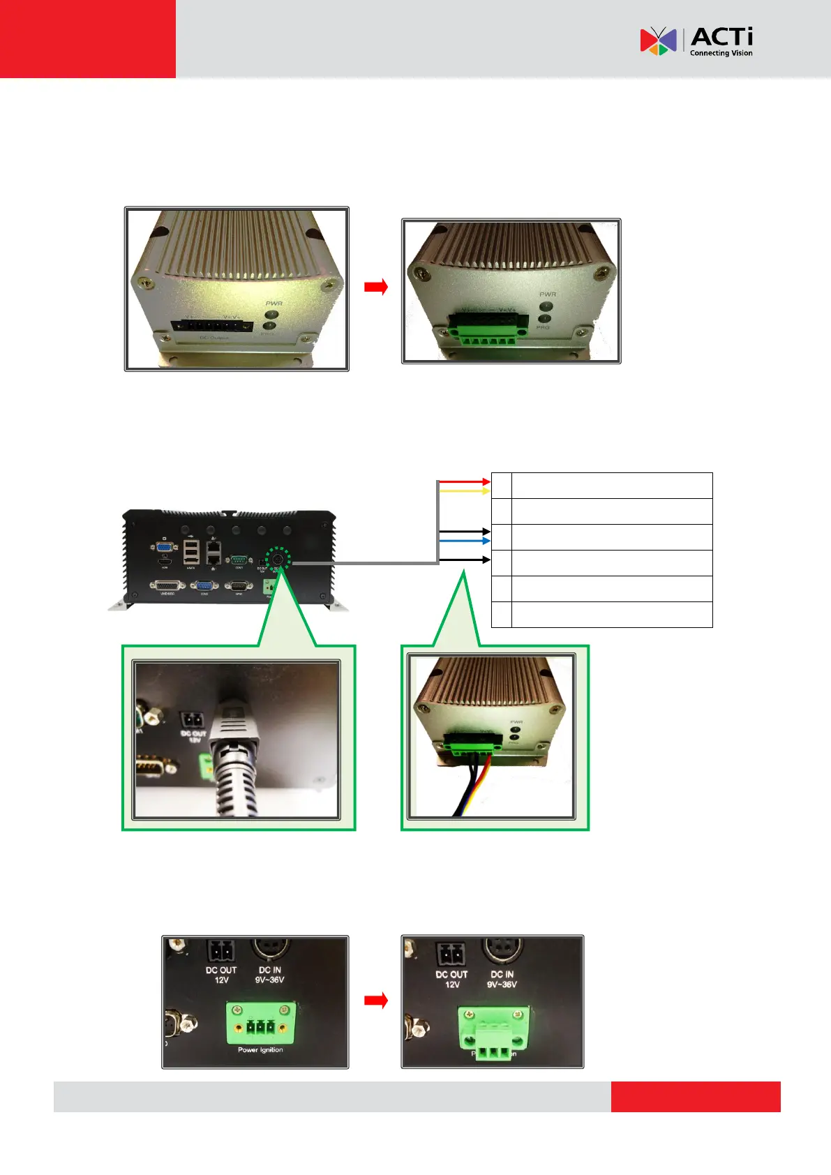
Step 2: Connect the module’s DC output to the MNR 310’s DC input
Attach and secure the 6-pin block connector to the power ignition control module’s power
output socket, marked as “DC Output”:
Connect the module’s DC output socket to MNR 310’s DC input using the power cord provided
with your MNR 310 by referring to the wiring definition and illustration below:
Step 3: Connect the module’s S3 control port to the MNR 310’s power ignition.
Attach and secure the 3-pin block connector provided with your MNR-310 device to the power
ignition socket on your MNR:
LVDS POWER OUT (+12V / 1A)