7351 Series Digital Multimeter Operation Manual
6.6 Comparator Output (7351E + Option 03)
6-14
6.6 Comparator Output (7351E + Option 03)
The comparator calculation result is output from the comparator output terminal (COMPARATOR) on the
rear panel as the TTL signal and the optical semiconductor relay contact signal.
Specifications
Connector
Dsub 9-pin
a. Optical semiconductor relay contact
Allowable contact voltage (for break) DC30 V
Allowable contact current DC120 mA
Withstand voltage between contact and GND 30 V
Contact operating time 1 ms or less
Contact output LO: 4 pin and 8 pin
HI: 3 pin and 7 pin
PASS: 2 pin and 6 pin
b. TTL output
Output level TTL
Maximum allowable applied voltage 12 V peak
Overload characteristics Short-circuit (continuous)
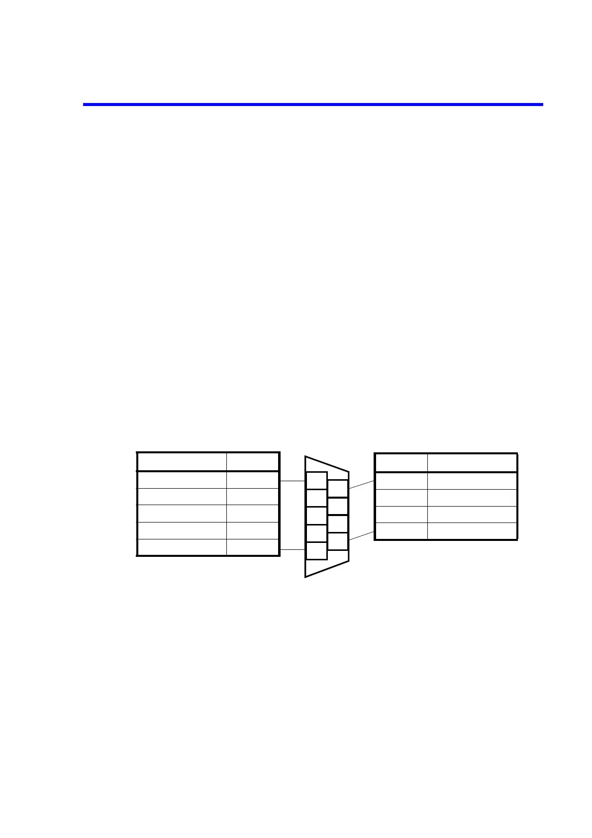
Figure 6-3 Signal Output Pin
Pin name Pin number
Signal GND 5
RELAY LO 4
RELAY HI 3
RELAY PASS 2
TTL PASS 1
3
2
5
4
1
8
7
9
6
Pin number Pin name
9 TTL FAIL
8 RELAY LO
7 RELAY HI
6 RELAY PASS