7351 Series Digital Multimeter Operation Manual
4.2.1 Measurement Functions
4-10
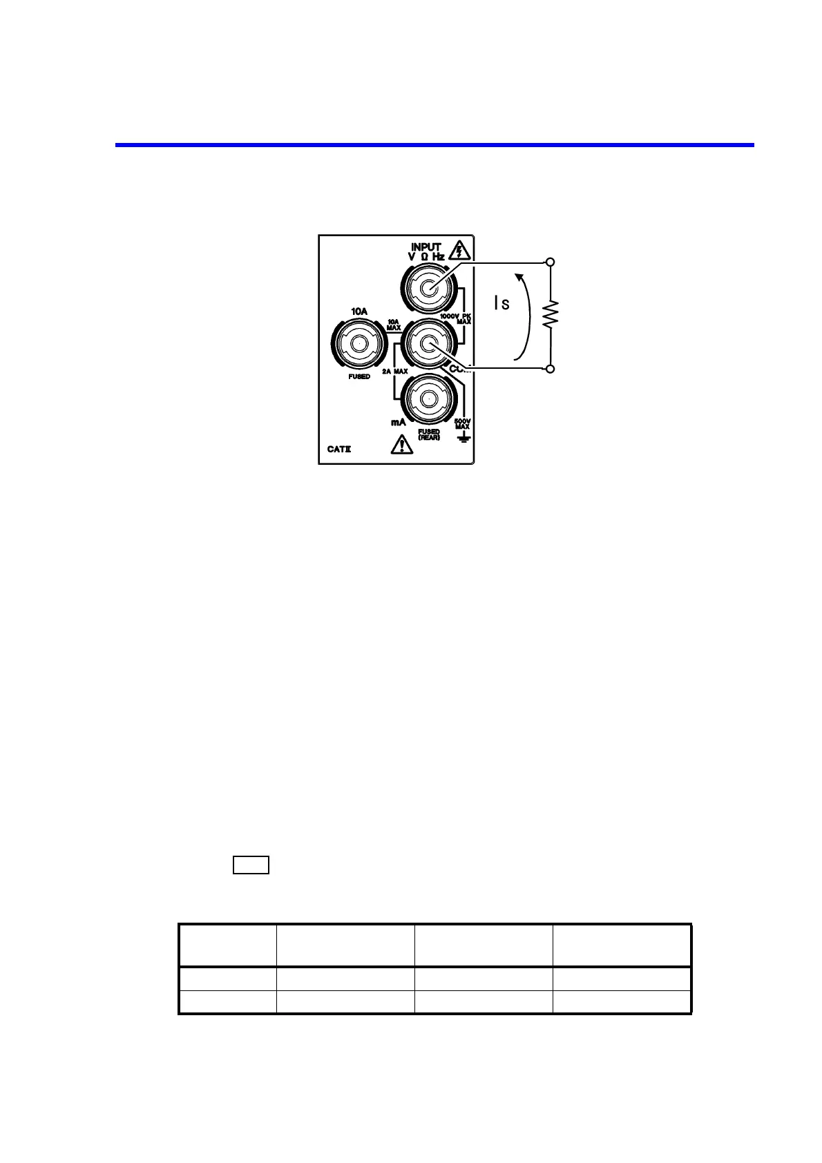
Figure 4-7 Resistance Measurement (2W and LP-2W)
The measurement result includes the input cable resistance and contact resistance. To reject these re-
sistance effects, short the tip of the input cable and set the NULL calculation to ON before the mea-
surement.
Ensure the following when in the high-resistance measurement to reduce the effect of the induction
noise.
• Shielding the DUT
• Using the A01001 input cable (sold separately) whose HI side is shielded.
• Securing the input cable to prevent movement
4.2.1.4 DC Current Measurement (DCI)
1. Input terminals differ depending on the measurement range.
<200 mA and 2000 mA ranges>
Connect a DUT to the mA and COM terminals on the front panel.
<10 A range>
Connect a DUT to the 10 A and COM terminals on the front panel.
2. Press .
Table 4-5 Maximum Allowable Applied Current and Protection Function (DCI)
Input terminal Measurement range
Maximum allowable
applied current
Protection function
mA 200 mA, 2000 mA 2 A F2A / 250 V Fuse
10 A 10 A 10 A F15A / 250 V Fuse