7351 Series Digital Multimeter Operation Manual
4.1.2 Rear Panel Description
4-5
4.1.2 Rear Panel Description
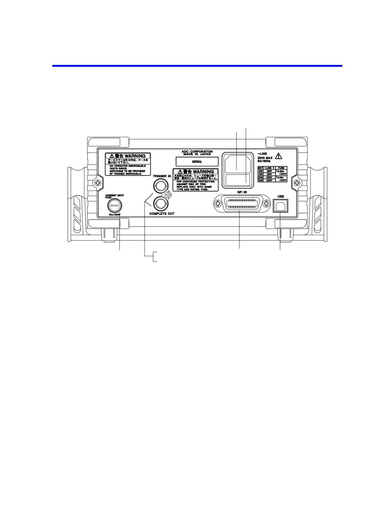
Figure 4-3 Rear Panel Description (7351A)
1. Power connector Used to supply the AC power by connecting the included power
cable (A01402).
2. Fuse holder assembly The power supply voltage can be selected from 100 V, 120 V, 220
V, and 240 V.
A slow-blow fuse is put.
3. USB connector Connector for USB
Used to output data and control remotely.
4. GPIB connector (7351A) Connector for GPIB
Used to output data and control remotely.
5. TRIGGER IN Used to input the external trigger.
(7351A,
7351E + Option 03)
6. COMPLETE OUT Outputs the complete signal of the measurement.
(7351A,
7351E + Option 03)
7. Overcurrent protection fuse Protects the overcurrent into the current input terminal (200 mA,
2000 mA range).