7351 Series Digital Multimeter Operation Manual
4.2.1 Measurement Functions
4-14
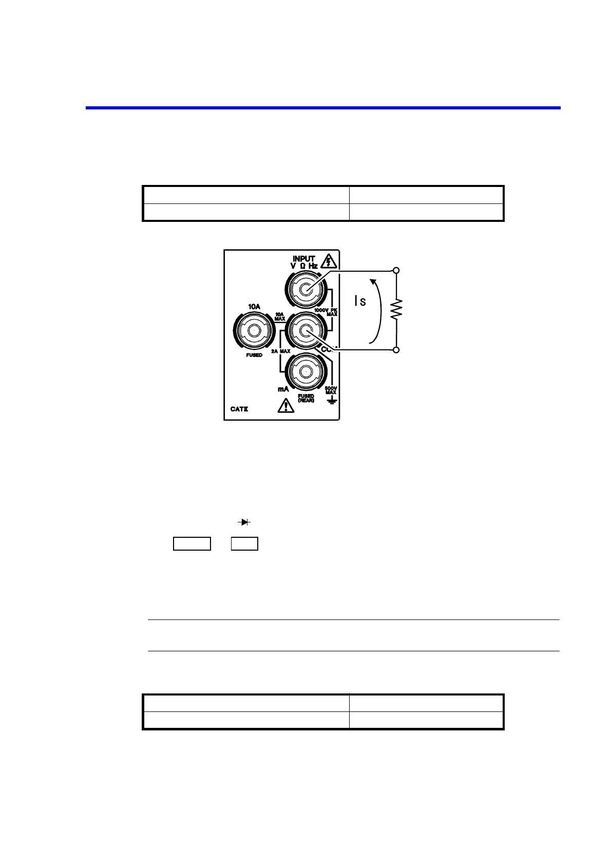
Figure 4-10 Continuity Measurement
4.2.1.7 Diode Measurement
1. Connect a DUT to the V and COM terminals on the front panel.
The diode indicator ( ) is activated.
2. Press and .
A current of approximately 1 mA is applied from the COM terminal to the V terminal, and the voltage
between both terminals is measured.
Measurement range 2000 mV
Measurement current 1 mA
WARNING: Do not apply voltage that exceeds the maximum allowable applied voltage. Fire or electric
shocks due to the failure of this instrument may occur.
Table 4-7 Maximum Allowable Applied Voltage (Continuity)
Between and COM terminals 1000 Vpeak
Between COM terminal and chassis (grounding) 500 V
Table 4-8 Maximum Allowable Applied Voltage (Diode)
Between V and COM terminals 1000 Vpeak
Between COM terminal and chassis (grounding) 500 V