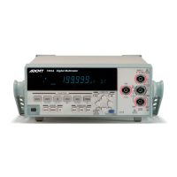
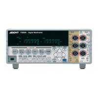
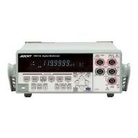
7351 Series Digital Multimeter Operation Manual
7.2 Interface Specifications
7-14
CAUTION: Option 03 is a factory option that is applied to 7351E only. This option cannot be added after instru-
ment delivery.
Comparator output (7351E + Option 03)
Output signal TTL Output: PASS/FAIL
Relay Output: PASS/Hi/Lo
(PASS/FAIL Output can be set individually)
Connector Dsub 9-pin
a.Optical semiconductor relay contact
Allowable contact voltage (for break) DC30 V
Allowable contact current DC120 mA
Withstand voltage between contact
and GND
30 V
Contact operating time Approximately 1 ms or less
b. TTL Output
Output level TTL Selecting the positive or negative logic
Maximum allowable applied voltage 12 Vpeak
External trigger signal
(7351A, 7351E + Option 03)
Connector BNC
Signal level TTL Detecting the falling edge
Pulse width 1 s or more
Complete signal output
(7351A, 7351E + Option 03)
Connector BNC
Signal level TTL Negative pulse
Sink Current 20 mA or below
Pulse width Approx. 100 s (7351A)
Approx. 900 s (7351E + Option 03)
Item Specifications