AESFill AF1C Machine Manual 14/58 Installation
To assemble the pump 4.1
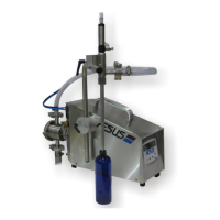
Figure 4-2: Pump Assembly
1. If removed, replace the U-cup drive shaft seal by
inserting the small diameter edge of the seal back into
the drive shaft hole recess.
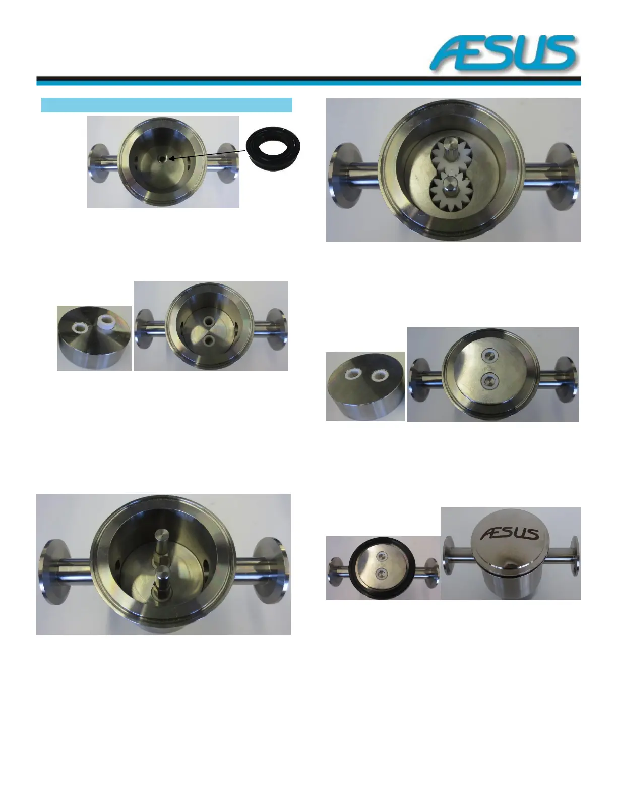
Figure 4-3: Pump Assembly 1
2. If removed, replace the longer bushing and one of the
smaller bushings into one of the bushing holders.
3. Place this bushing holder into the pump vault making
sure that the longer bushing inserts into the drive shaft
hole recess at the bottom of the pump vault. Both
bushings should be flush with the top of the bushing
holder.
Figure 4-4: Pump Assembly 2
4. Place the drive shaft (longer shaft) through the long
bushing and the shaft seal. The hexagonal section of the
shaft should come up against the end of the bushing
insert.
5. Similarly, place the Idler shaft into the other hole.
Figure 4-5: Pump Assembly 3
6. Slide both gears onto the shafts making sure that they
locate on the hexagonal sections of the shafts.
7. Place the gear chamber into the pump vault on top of the
bushing holder.
Figure 4-6: Pump Assembly 4
8. If removed, insert the two other short bushings into the
second bushing holder. Now slide the second bushing
holder over the two shafts. When this piece is in place, it
should be just above the top flange of the pump body.
Figure 4-7: Pump Assembly 5
9. Place the end cap sealing ring on the top flange of the
pump vault. Place the end cap on top of the seal. Fasten
the 3” (7.5 cm) sanitary clamp and tighten approximately
two turns after contact to seal the end cap to the pump
vault.