AESFill AF1C Machine Manual 16/58 Installation
Nozzle 4.2
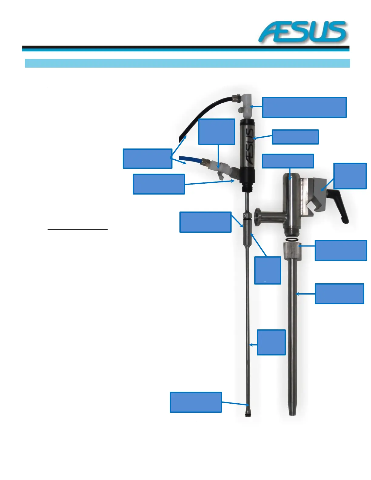
4.2.1 Standard Nozzles
The nozzle consists of 11 pieces:
1. 1 Quick Connect Air Fitting
2. 1 90 degree Quick Connect Air Fitting
3. 1 Air Tubing Duo (Black and Blue)
4. 1 Air Cylinder
5. 1 Nozzle Stem with Set Screw
6. 1 Stem O-Ring Top
7. 1 Stem O-Ring Bottom
8. 1 Nozzle Body
9. 1 Clamp with Handle
10. 1 Nozzle Spout O-Ring
11. 1 Nozzle Spout
12. 1 Nozzle Stem
4.2.2 To assemble the nozzle:
**Note: Before assembly, all O-rings should be wetted with an approved lubricant, or at least with the
product being filled.
1. Install the O-rings (#6 & #7) onto the nozzle stem (#5). Assemble the
plunger onto the air cylinder (#4). The position of the plunger within the
completed nozzle must be adjusted by threading more or less of the air
cylinder into the stem. This is to set the correct closed position of the
nozzle stem.
2. Screw in the small set screw, carefully aligning it with the groove on the air
cylinder, screw it in all the way snug and then loosen it by ¼ turn. The set
screw should be loose, but in far enough so as not to protrude. This way
the stem will hang centrally, and not be forced over to one side.
3. Screw the air cylinder/nozzle stem unit into the nozzle body (#8). Again do
not tighten, leave it a minimum ½ thread loose, at a handy orientation for
the airlines.
4. Place the O-Ring (#10) into the Nozzle Spout (#11) and then slide it onto
the plunger. You may need to push the plunger up so it is easier to get the
nozzle spout on. Now screw the nozzle spout onto the nozzle body.
2–90 Degree Quick Connect Air
Fitting
1- Quick
Connect
Air Fitting
Figure 4-10: Standard Nozzle Assembly