3 Measure the holdoff time.
Press [
Marker
], [
REFERENCE SETUP
].
Using the knob, move the marker to the start of the first clean edge.
Press [
REFERENCE TO MARKER
].
Now use the knob to move the marker past any inappropriate transitions on the edge of
the signal.
Note the Xr marker value at the top of the grid.
4 Specify the holdoff time.
Press [
Input
],[
TACHOMETR SETUP
], [
HOLDOFF TIME
], then press [
Mkr Value
].
5 Verify the tachometer input.
Press [
Scale
], [
AXES SCAL MARKERS
], then press [
FULL SCALE
].
Press [
Inst Mode
] [
ORDER ANALYSIS
].
Press [
Meas Data
] [
PWR SPEC CHANNEL 1
].
Press [
Start
].
The Xr marker value displayed in Step 3 is specified as the holdoff time in Step 4.
The tachometer indicator at the top of the display is reading the tachometer input
signal from the rear panel. The display is showing the tachometer signal from
Channel 1.
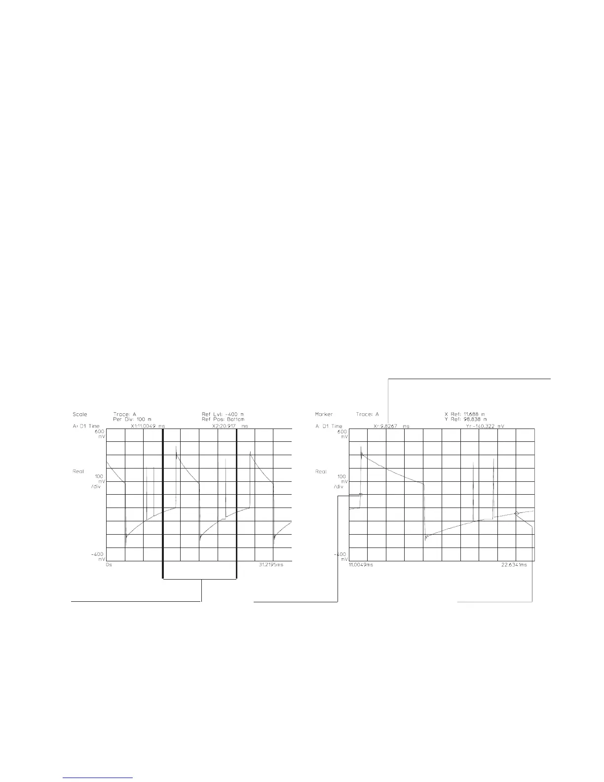
[SCALE AT MARKER]
displays only that part of the
trace between the [AXES
SCALE MARKER]
Marker Reference
Relative Marker value
specifies holdoff time
Relative Marker
Agilent 35670A Quick Start Guide Making Measurements
43
 Loading...


