q
Step 2. Check the CPU signals to the Display assembly.
•
Set the power switch to on ( l ).
•
Using a logic probe, check that the following TTL signals are toggling.
Test Location Signal Name In/Out
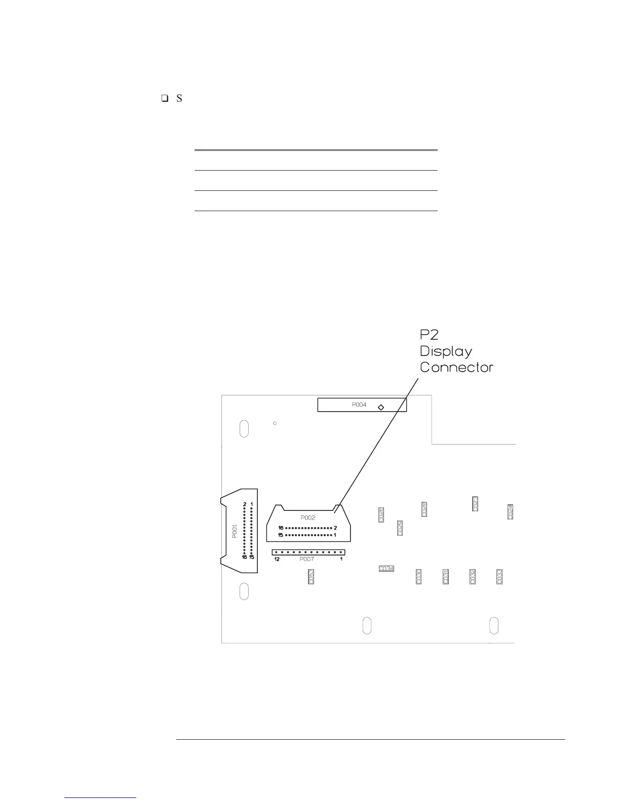
A7 P2(9) VSYNCEL A7 Out
A7 P2(11) HSYNCELn A7 Out
A7 P2(13) VCLK A7 Out
A7 P2(15) VID A7 Out
•
If the signals are incorrect, do the following:
•
Set the power switch to off ( O ).
•
Disconnect the display cable from A7 P2.
•
Set the power switch to on ( l ).
•
Check the signals again.
•
If the signals are now correct, the A101 Display assembly is probably faulty.
A7 Component Locator, Circuit Side
Agilent 35670A Troubleshooting the Analyzer
To troubleshoot display failures
4-23

 Loading...


