q
Step 3. Check the periodic chirp output.
•
Press the following keys:
[
DC OFFSET ]
0
[ V ]
[
LEVEL ]
1
[ Vpk ]
[
PERIODIC CHIRP ]
•
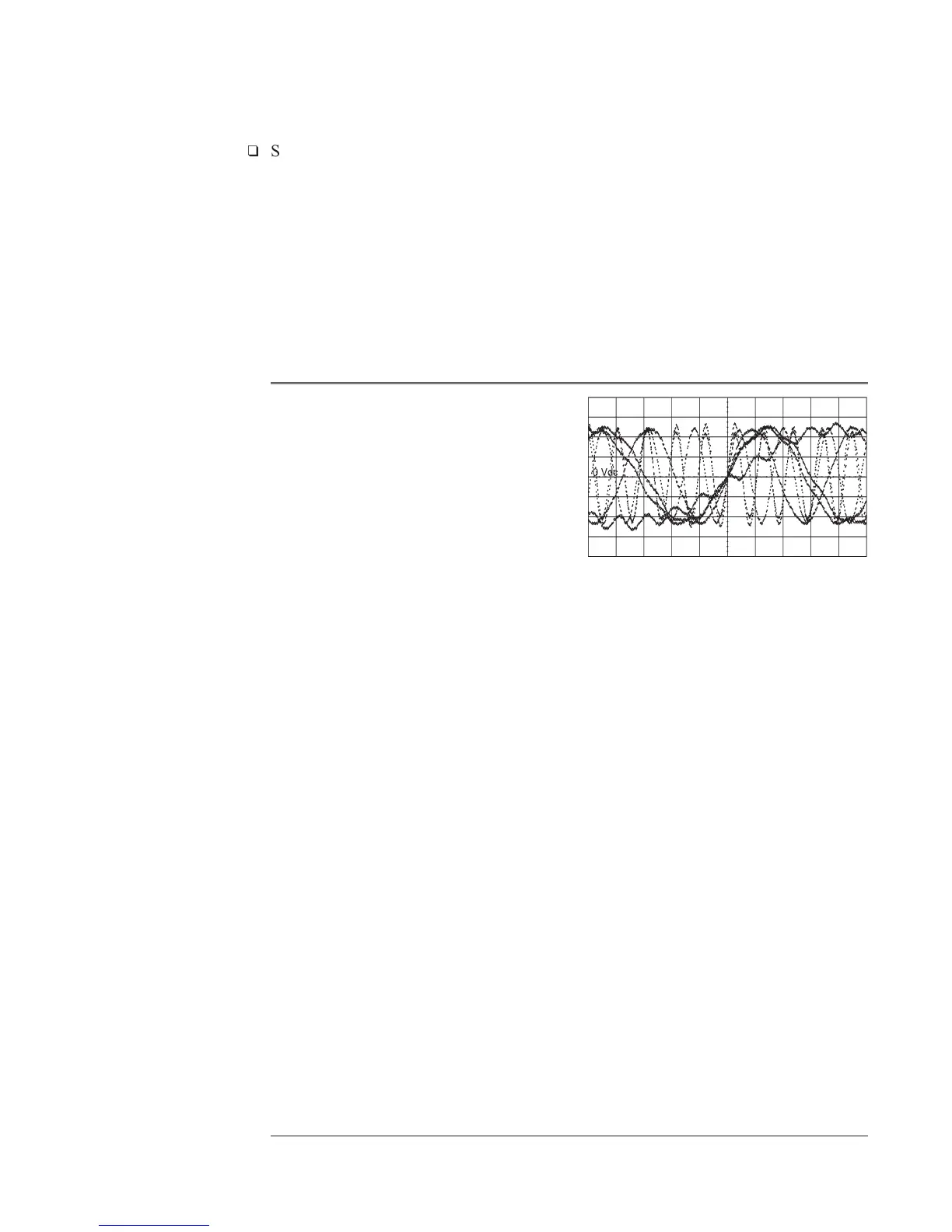
Using an an oscilloscope and a 1:1 probe, check the following signal.
Oscilloscope Setup Parameters Waveform
Connect CH1 to A5 TP8 Amplitude
Time
Duty Cycle
Pulse shape
Time
Relationship
Periodic Chirp
CH1 V/div
Input Impedance
CH1 Coupling
Probe Atten
Display Mode
Averaging
Time/div
Trigger
Trig Src
300 V/div
50 Ω
dc
1
Repetitive
off
10 µs/div
Trg’d
Sweep
Chan1
•
If the signal is incorrect, the A5 Analog assembly is probably faulty.
Agilent 35670A Troubleshooting the Analyzer
To troubleshoot source and calibrator failures
4-47

 Loading...


