q
Step 4. Check the calibrator output.
•
Set the power switch to off ( O ).
•
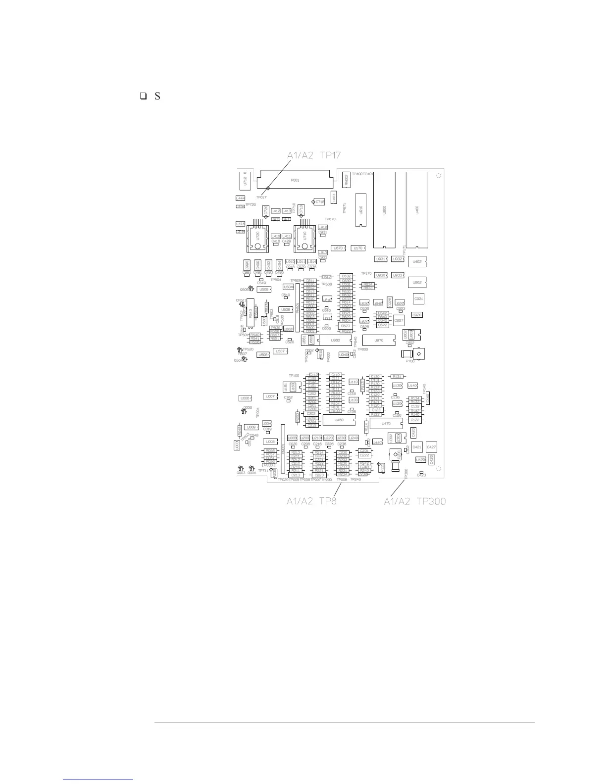
Remove the A1/A2 Input assembly and attach a test clip patch cord to TP
17. Connect a 10:1 oscilloscope probe to the patch cord and TP 8 (ground).
•
Reinstall the Input assembly in the card nest with patch cord and probe
attacted.
•
Set the power switch to on ( l ).
Troubleshooting the Analyzer Agilent 35670A
To troubleshoot source and calibrator failures
4-48

 Loading...


