I2C/SPI Triggering and Serial Decode 24
Agilent InfiniiVision 3000 X-Series Oscilloscopes User's Guide 371
This determines which clock edge the oscilloscope will use to latch
the serial data. When Display Info is enabled, the graphic changes to
show the current state of the clock signal.
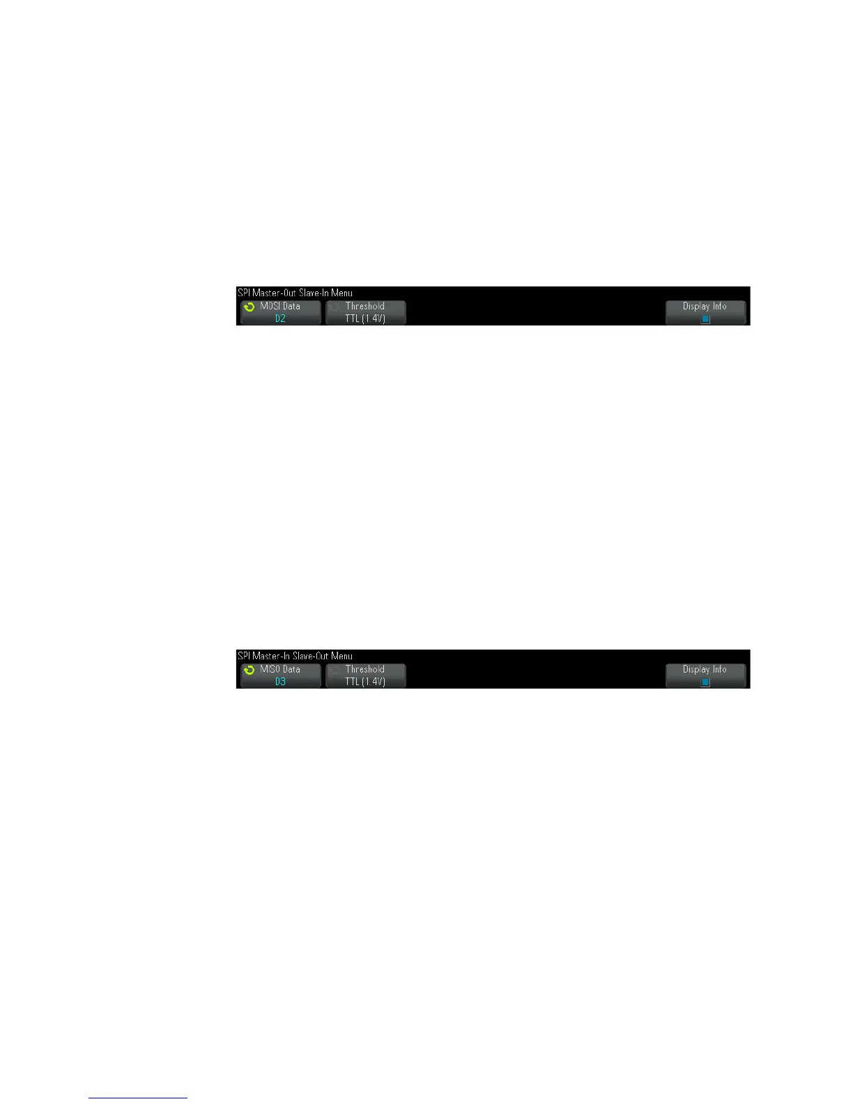
7 Press the MOSI softkey to open the SPI Master- Out Slave- In Menu.
In the SPI Master- Out Slave- In Menu:
a Press the MOSI Data softkey; then, turn the Entry knob to select the
channel that is connected to a SPI serial data line. (If the channel
you selected is off, switch it on.)
The MOSI label for the source channel is automatically set.
b Press the Threshold softkey; then, turn the Entry knob to select the
MOSI signal threshold voltage level.
The threshold voltage level is used in decoding, and it will become
the trigger level when the trigger type is set to the selected serial
decode slot.
8 (Optional) Press the MISO softkey to open the SPI Master- In Slave-Out
Menu.
In the SPI Master- In Slave-Out Menu:
a Press the MISO Data softkey; then, turn the Entry knob to select the
channel that is connected to a second SPI serial data line. (If the
channel you selected is off, switch it on.)
The MISO label for the source channel is automatically set.
b Press the Threshold softkey; then, turn the Entry knob to select the
MISO signal threshold voltage level.
The threshold voltage level is used in decoding, and it will become
the trigger level when the trigger type is set to the selected serial
decode slot.

 Loading...


