Chapter 4 Settings and Test
24
STOP
START
2
31
AC220V-240V 50/60Hz
700VA MAX
FUSE AC250V T10A
MAKE SURE TO CONNECT THE PROTECTIVE
GROUNDING
ONLY FUSE WITH THE SAME TYPE AND
RATINGS CAN BE USED
REFER SERVICING TO QUALIFIED PERSONNEL
WARNNING
NC
NC
N
L
AC 300V
50/60Hz
25A MAX
DUT
POWER
EXT-COM
COM
SIGNAL OUTPUTSIGNAL INPUT
SCN2SCN3 SCN1 SCN0
STB
PM1
PM0
PM2
NC
COM
GPIBLAN
EXT-PLC-B EXT-PLC-A
PLC
ALARM
REMOTE
BAR CODE INPUT
H.V./L H.V./N
HIGH VOLTAGE
5.0kV AC MAX
6.0kV DC MAX
CURRENT-
SENSE-SENSE+
CURRENT+
MAX 10A MAX 16A
TESTING FIXTURE-16A
Ainuo
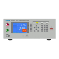
Figure 4-1-1 (1) 9640BV3 connection test box and ground test clamp schematic
1) Connect the four wires on the test box as shown, and lock the terminals.
2) Connect the two wires on the ground test clamp as shown in the figure, and lock the
terminals.
6.0kV DC MAX
5.0kV AC MAX
HIGH VOLTAGE
A5 A6
A2A1
A3
A4
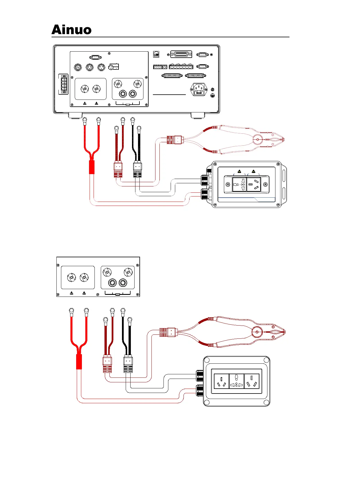
Figure 4-1-1 (2) 9651BV3/9651CV3 connection test box and ground test clamp
1) After passing the four wires on the test box through the wire hole at the rear of the