Chapter 2 Overview
9
2.5 AN9651BV3/AN9651CV3 installation and connection
2.5.1 AN9651BV3Assembly wiring
The comprehensive test system needs to install the corresponding test fixtures and
accessories, and the input power supply can be used normally. Please refer to the steps shown in
Figure 2-1 for the installation and connection.
Note: Make sure that the power supply is single-phase AC220V -240V, 50/60Hz.
Step 1: Prepare the
device for installation
▲ Put the power switch
of the whole machine in
the “OFF” position;
▲ Turn off the power
switch for analysis.
Step 2: Install the
fastening joint
▲ Remove the black rubber
ring that comes with it, and
replace it with the
fastening joint accessory.
Step 3: Connect the test
fixture
▲ Pass the A1—A6 test
leads of the test box and
test tongs through the
wiring holes, and connect
them one-to-one with the A1
—A6 terminals of the
analyzer, and fasten them;
Note: You need to remove the
top baffle at the top of the
cabinet after connecting.
After the connection is
completed, install the
baffle.
Step 4: Connect the device
power input cable and
connect to the power grid.
▲The power supply line
should be selected according
to the power of the measured
body. The maximum input
capacity is 6kVA.
Step 5: Power on the
device
▲ Put the power switch
of the whole machine in
the “ON” position;
▲ Turn on the analyzer
power switch.
Note 2: How to turn off
the device
▲Turn off the analyzer
power switch.
▲ Put the power switch
of the whole machine in
the “OFF” position;
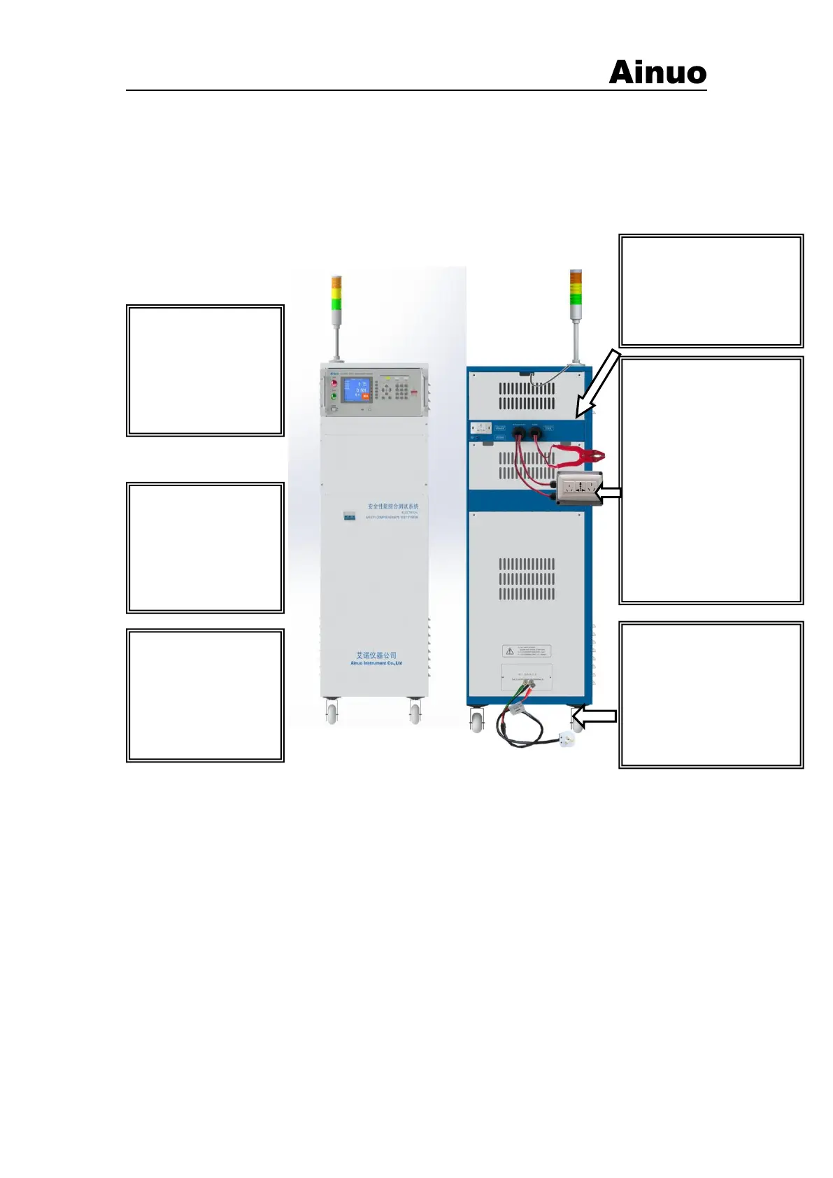
Figure 2-5-1 Wiring diagram of the comprehensive test system
Note: The comprehensive test system is a 220V/50Hz power supply system. The maximum
power required by the system is 6kVA (including the operating power of the product under test).
Please confirm that the connected power supply can provide the required frequency and power
capacity. Do not use power supplies that do not meet the above requirements to avoid equipment
damage.
2.5.1 AN9651CV3Assembly wiring
①Hardware installation: The hardware devices of AN9651CV3 comprehensive
measurement system are installed in a chassis. When installing, please refer to the following
installation steps. For the detailed hardware configuration and installation sequence, please refer to
the hardware configuration diagram included with the system. The following only provides the
installation method of the general standard configuration of the AN9651CV3 comprehensive
measurement system.
Installation steps:
(1) Fix the display and alarm light on the upper part of the chassis and tighten the screws, as