Annex A Test Principle
54
Annex A Test Principle
Guide:
A.1 Block Diagram
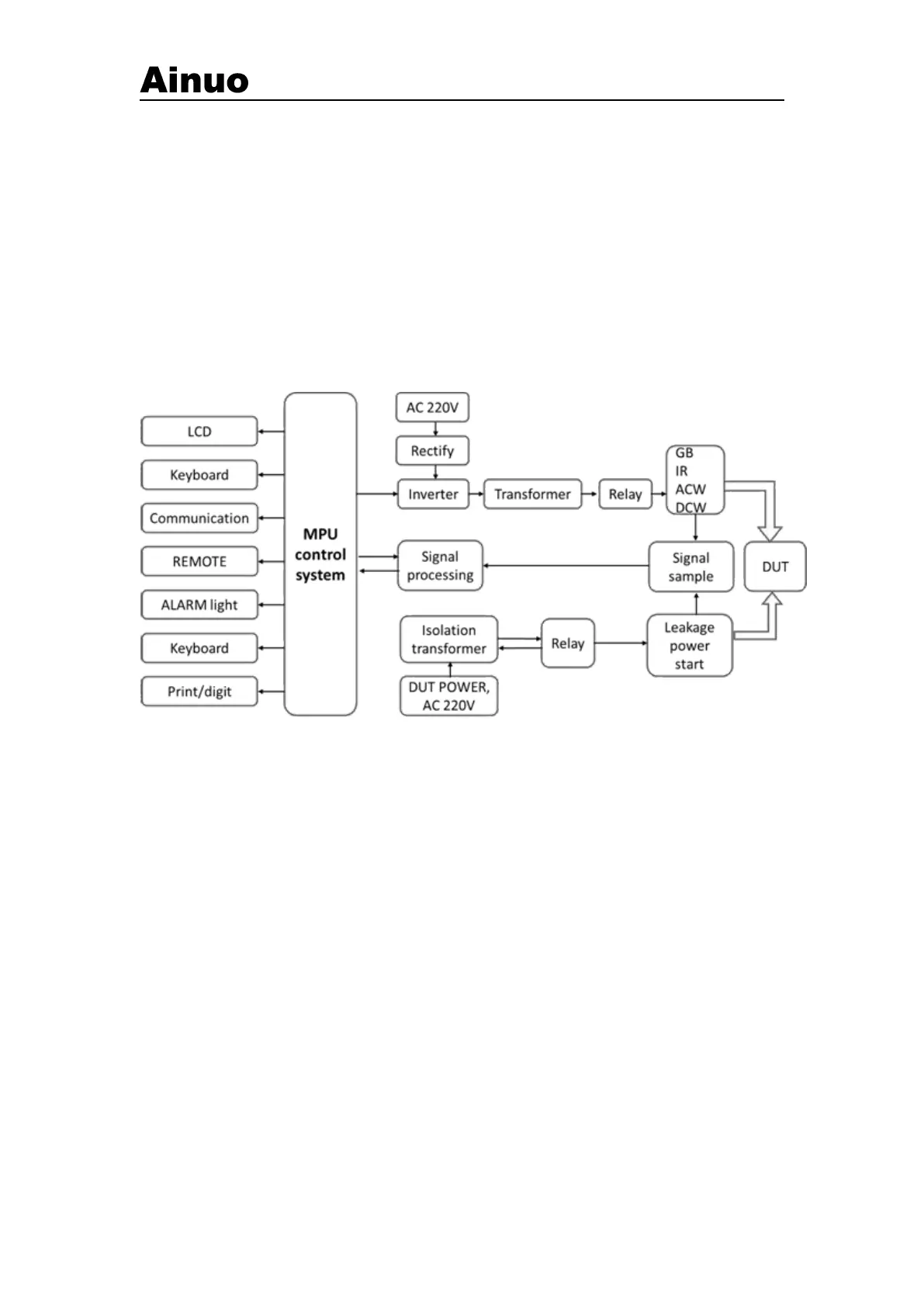
Figure A-1-1 Block Diagram
A.2 Test Principle
This AN9640BF(V3) series analyzer adopts DSP microprocessor for control, completing
A/D convertion, output control, data process and management of display, key and serial
communication etc.
In this system, the SPWM signal is generated by the processor DSP, driven via the high
power MOS transistor, forming 50Hz or 60Hz sine wave through the filter circuit, which
generates ACW/DCW (5000Vac/6000VDC), GR (32A) and IR (2500VDC) source output
signal through the transformer. For LC, PA and ST, provide DUT with power input via
external power supply.
The source output signals and the measured voltage or current signal is sampled via the
voltage and current sensors for measuring. The value obtained is converted by the A/D
converter, entering ARM processor for operation and judged as to PASS or FAIL etc., and the
results are displayed on the LCD.