Chapter 5 Interface
43
5.2 REMOTE
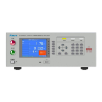
Active signal input interface, 3P aero socket (male), as shown in Figure 5-2-1.
Figure 5-2-1 REMOTE (male)
Definition of pins:
3) 1: Common (Low end, GND)
The optional attachment is the remote control box. Insert the 3P aero plug of the remote
control box into the 3P remote control socket on the left panel. The function of START/STOP
keys are the same as those on the front panel.
For self-made remote control switch, use passive non
self-lock switch!
5.3 PLC
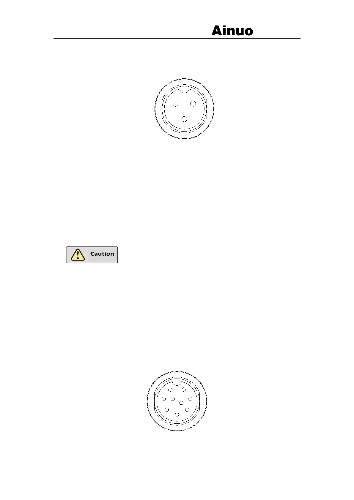
This analyzer is fit with a 9-pin aviation plug (male) to provide PLC remote I/O signal
(may be connected with PLC controller) and digital test state output signal, as shown in
Figure 5-4-1. These terminals must match 9-pin aviation plugs (female), which is prepared by
the operator. For optimum effect, it is recommended to use shielded cables as control line and
output data line. To avoid forming a circuit of the shielded cables and ensure shielding effect,
ground the shield net at one end of the shielded cable.
Figure 5-3-1 PLC port (male)