Chapter 5 Interface
42
Chapter 5 Interface
Guide:
SIGNAL INPUT/SIGNAL OUTPUT
5.1 ALARM
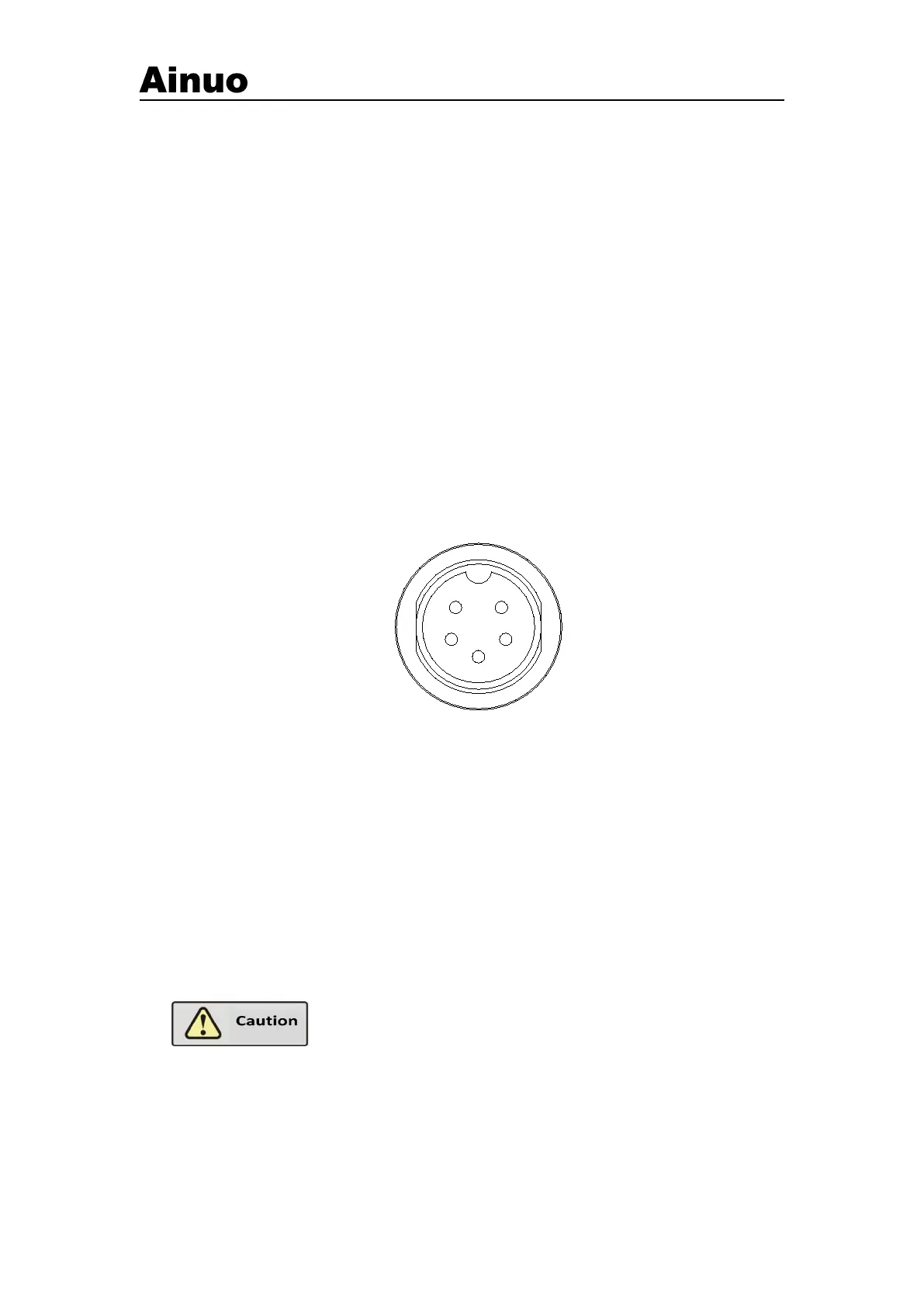
Active signal output, using 5P aero socket (male), as shown in Figure 5-1-1.
Figure 5-1-1 ALARM socket (male)
Definition of pins:
3) 3 - 4 ON: FAIL , or abnormal alarm
4) 4: Common (High end, +12VSW)
The optional attachment is 3-color ALARM. Insert the 5P aero plug of 3-color ALARM into
the 5P ALARM socket on the left panel.
During self-check as booting, 1-4, 2-4 and 3-4 will be ON
at the same time. Now the maximum allowable total output current is 450mA.
The maximum allowable output current for single channel is 150mA. For
self-made ALARM light, pay attention to this point!