Chapter 4 Settings and Test
25
comprehensive measurement system, according to the markings on the wire, one-to-one
correspondence, connect and fasten the terminals (A1, A2, A4, A6);
2) After passing the two wires on the grounding test pliers through the wire hole at the rear of
the comprehensive measurement system, according to the markings on the wire, one-to-one
correspondence, connect and fasten the terminals (A3, A5);
3) Tighten the locking device on the cable hole.
Warning! Make sure to place GB clamp and test box on an
insulation pad.
4.1.2 Connect input power of the instrument
Input Power: single phase 220V±10%, 50Hz±5%. Fuse spec: 250V/10A fast blown. Apply the
power line.
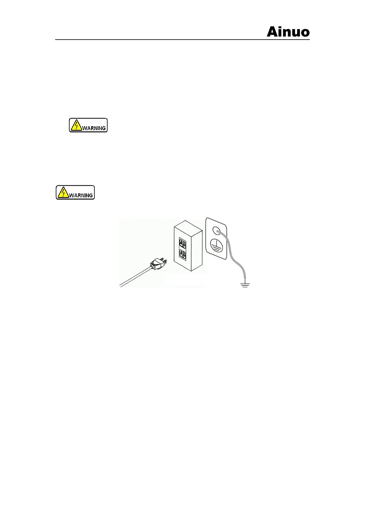
Warning! To ensure the safety and measurement accuracy , connect the protective
grounding well!
(a) Connect to grounding by 3-core power line
(b) Connect to grounding by the GND terminal on the rear panel
Figure 4-1-3 Connect to protective grounding
There are two grounding connection methods, as shown in Figure 4-1-3.
1) The instrument fixes with 3-core power line. Connect the power line to the socket with
earth line
2) Connect the grounding terminal of instrument to the grounding terminal of input power.
4.1.3 Connect DUT
DUT wire connections is as shown in Figure 4-1-4.