Chapter 5 Interface
46
3: TXD, send data
5: GND, ground
5.8 SIGNAL INPUT/SIGNAL OUTPUT
Use a 6-Pin European terminal, external adjustment device to select the group, up to 7
adjustable groups.
The user can input PM0, PM1 and PM2 three digit codes to choose any one of the 8
groups. The selection is valid at the rising edge of STB, as shown in Table 5-4-2:
Table 5-4-2 Remote signals
Note:
1, 0----Open, 1---- Closed;
2, STB from closed to open, deemed as a valid rising edge. For the control time, see
Figure 5-2 Timing of remote control test;
3, “Open” means open-circuit with COM. “Closed” means short-circuit with COM.
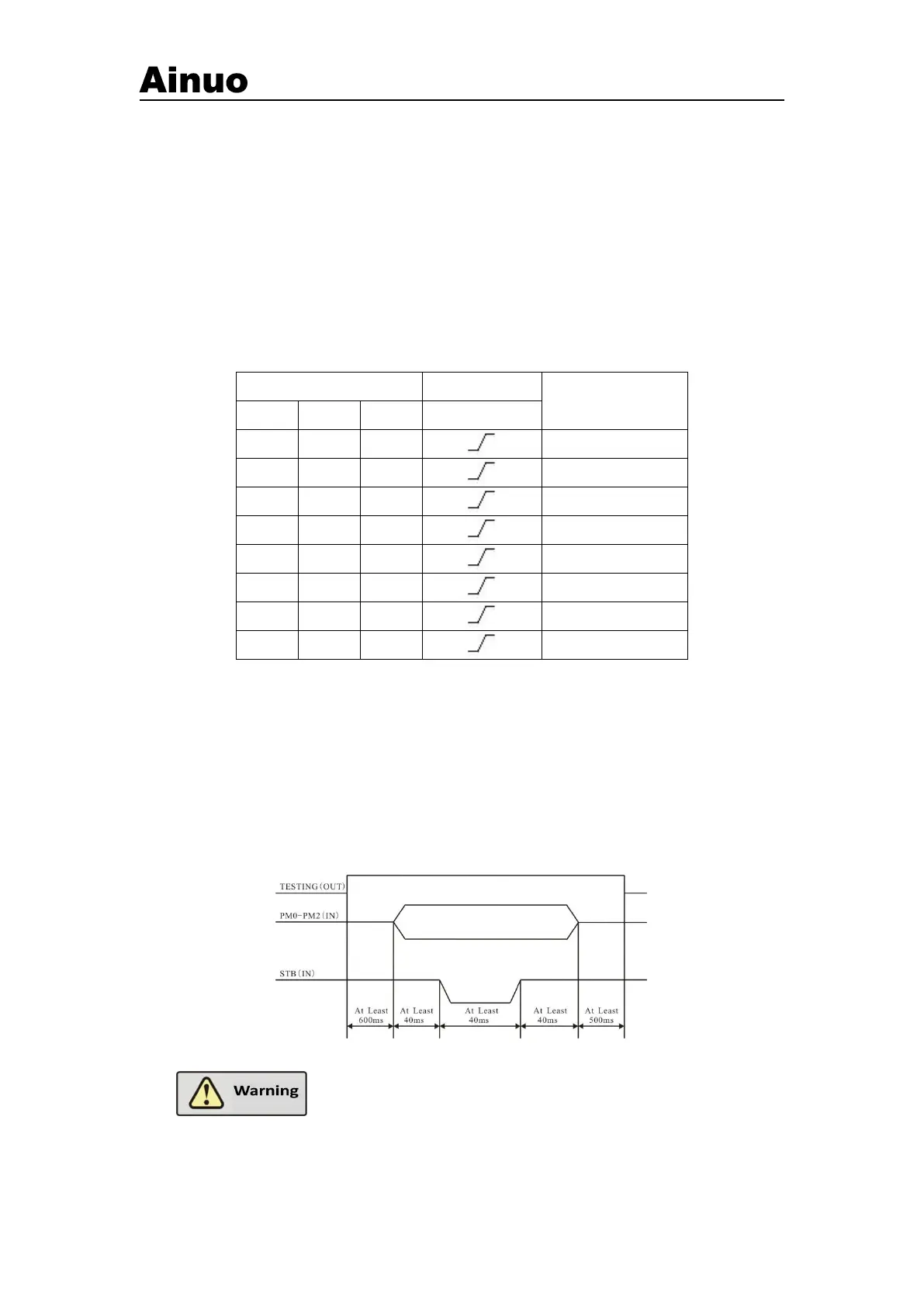
The PLC will choose group following the timing in Figure 5-4-2.
Figure 5-4-2 Timing of remote selection of group
The TEST in Figure 5-4-2 is output signal. Do not call any
groups during testing, otherwise, the call instruction will be ignored!